background image

7

OGÓLNE INSTRUKCJE MONTAŻU.

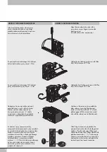
Zwolnienie pinu z elektrycznego gniazda 

wielopinowego.

W przypadku potrzeby wypięcia któregoś z 

pinów należy użyć np. wkrętaka płaskiego 

wkładając go do odpowiedniego otworu 

(patrz rysunek obok). Następnie  po jego 

lekkim wciśnięciu pociągnąć za przewód.

Releasing a contact from the D-sub connector

Insert a small cutting screwdriver into the 

window corresponding to the contact to 

remove. 

Press gently with the screwdriver and extract 

the wire in the direction indicated.

GENERAL ASSEMBLY INSTRUCTIONS

Zwolnienie wtyczki z elektrozaworu.

W przypadku potrzeby wypięcia wtyczki 

należy w miejscu pokazanym na rysunku 

wcisnąć zapadkę za pomocą wkrętaka lub 

palca i pociągnąć we wskazanym kierunku.

Releasing the connector from the electro-pilot

Press the point indicated with the screw driver 

or your fingers and extract the connector in 

the direction indicated.

Montaż wyspy do szyny DIN za pomocą uchwytów.

Przymocować uchwyty zarówno na płycie początkowej (A) jak i na 

końcowej (B) za pomocą śrub w zestawie Rys. 1. Następnie wyspę 

przyłożyć tylną częścią do szyny DIN, w celu jej zaczepienia za uchwyt 

i nieznacznie unieść w określonym kierunku (patrz Rys. 2). 
W celu wypięcia wyspy z szyny DIN przyłożyć siłę w kierunku 

oznaczonym na Rys. 3.

Fitting the connection brackets to a DIN bar

Fix the brackets both onto blind terminal B and input terminal A with the 

screws supplied. (Fig.1). Fit the rear part of the bracket to the DIN bar

in the direction indicated to obtain engagement. (Fig. 2)

For release from the DIN bar, use force in the direction indicated. (Fig.3)

Fig. 1

Fig. 2

Fig. 3

25 Masa (-) /25

 Com (-) 

B

A

A

A

B

A

A

A

B

A

A

A

Содержание MULTIMACH

Страница 1: ...GB USER MANUAL MULTIMACH MULTIMACH INSTRUKCJA U YTKOWNIKA PL...

Страница 2: ...h osadczych w poprzedzaj cych modu ach Continue in the same way to assemble the other valves as far as the blind terminal Make sure that the small teeth A of each plate engage with the successive ones...

Страница 3: ...0 valve plug in connector kit code 0226180401 for the thirteenth position onwards ELECTRIC WIRING Zacisk wsp lnego czarnego przewodu umie ci w odpowiednim gnie dzie przy cza elektrycznego oznaczonego...

Страница 4: ...common wires by inserting them into the protection hood and connect them in the most suitable position exploiting the space available Po monta u przewod w elektrycznych zamykamy drzwiczki obudowy End...

Страница 5: ...creasing 1 2 3 4 and from position No 9 and decreasing 9 8 without missing any positions see view Z Check that the number of male contacts is equal to the number of electro pilots 1 Connect the negati...

Страница 6: ...e to contact 1 of the 25 pole D sub connector the LED of the electro pilot 1 comes on Repeat the operation for all the electro pilots connected max 24 electro pilots WIRING DIAGRAM AND ELECTRICAL TEST...

Страница 7: ...zanym kierunku Releasing the connector from the electro pilot Press the point indicated with the screw driver or your fingers and extract the connector in the direction indicated Monta wyspy do szyny...

Страница 8: ...MINIATURYZOWANYCH Z CZY WTYKOWYCH 8 OZNACZONA W INDEKSIE LITER L I POSIADAJ CA ROWKI NA PIER CIENIU ZWALNIAJ CYM NIE JEST KOMPATYBILNA ZE Z CZAMI R7 R8 I R9 8 STARSZEJ SERII NOTE For tube 8 DO NOT USE...

Отзывы: