Page of 33
14
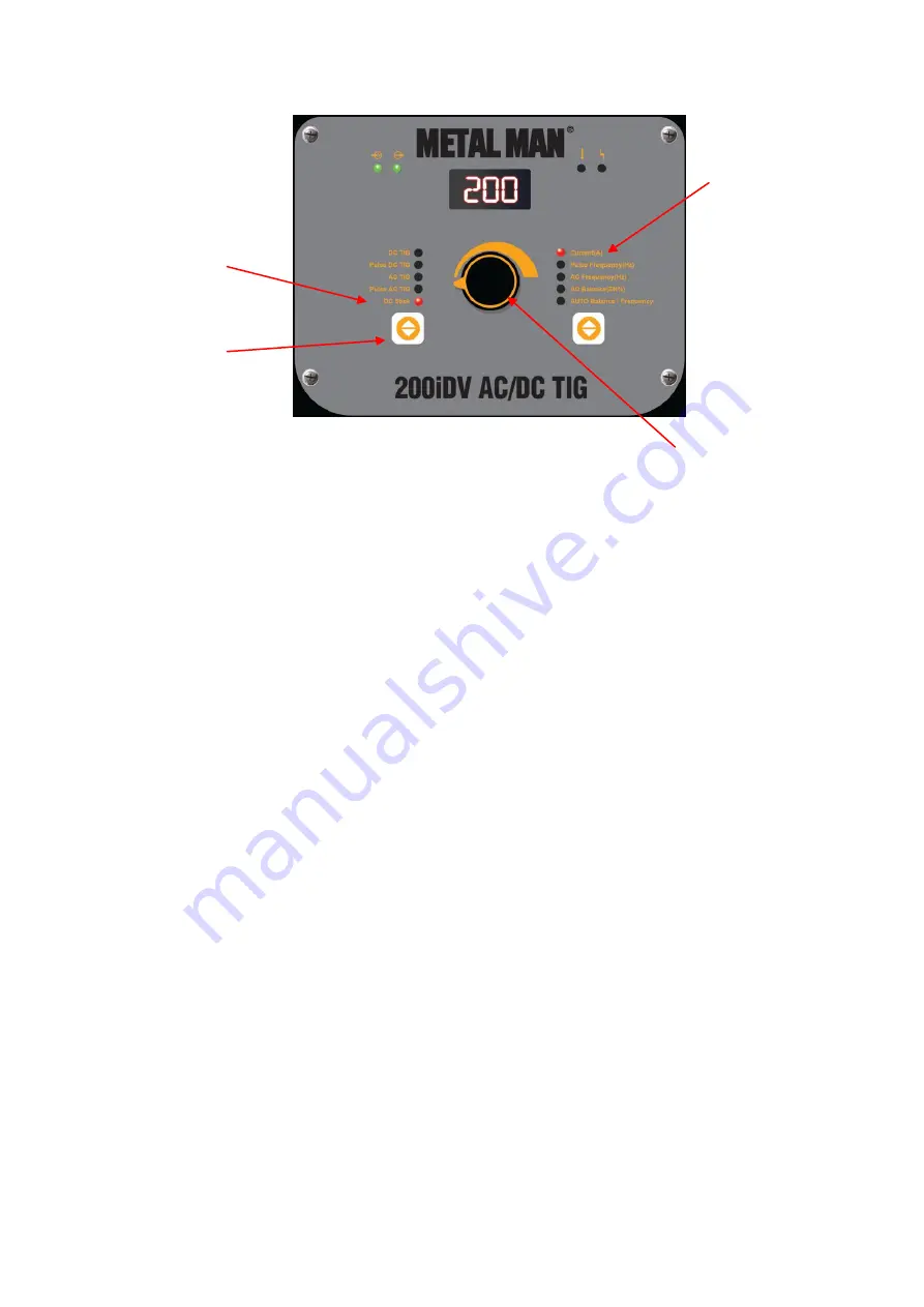
a. See the ASSEMBLY section for the correct welding accessories connections for DC Stick
Welding.
b. Turn the input power switch ON.
c. Press the button below the weld process indicators until the weld process indicator light
next to DC Stick is on.
d. Press the button below the weld parameter indicator lights until the Indicator Light is ON
for the Current (A) Weld Parameter.
e. The Digital Meter is displaying the Current (A) setting.
f. Turn the Parameter Adjustment Control until the Digital Meter displays the desired Current
(A) setting.
3. DC TIG SET-UP
a. See the ASSEMBLY section for the correct welding accessories connections for DC TIG
Welding.
b. Turn the input power switch ON.
c. Press the Weld Process Selector button until the Weld Process Indicator Light next to DC
TIG is on.
i. If the operator wants to use Pulse DC TIG, press the Weld Process Selector until
the Weld Process Indicator Light next to Pulse DC TIG is on.
d. Press the Weld Parameter Selector button until the Indicator Light is ON for the Current
(A) Weld Parameter.
e. The Digital Meter is displaying the Current (A) setting.
Weld Process
Indicator Lights
Push to Sequence
Through Weld
Processes
Weld Parameter
Indicator Lights
Weld Parameter
Adjustment
Содержание 200iDV
Страница 29: ...Page of 33 29 MAIN CIRCUIT CHART ...
Страница 30: ...Page of 33 30 DIAGRAM PARTS LIST ...


