Metal-Fach ecoMAX860P TOUCH Скачать руководство пользователя страница 28

28 


12.11


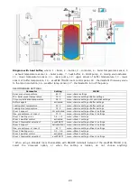
Connection of boiler's room 
thermostat 


Note:  the  boiler  room  thermostat 
should  be  switched  off  if  the  whole 
central  heating  system  of  the 
building is supplied through a mixing 
valve equipped with electric servo.  

The  regulator  may  work  with  mechanical  or 
electronic room thermostat, which opens the 
contacts  once  the  preset  temperature  has 
been achieved. 
Set-up the operation of room thermostat in:  
Boiler  settings 

  Room  thermostat 


Thermostat selection 

 Universal 


Once  the  preset  room  temperature 
has been reached, thermostat opens 
its  contacts  and  the  display  shows:  

Once  the  temperature  in  the  room,  in  which 
the room thermostat is installed, has reached 
the  preset  value,  regulator  reduces  the 
preset boiler temperature by the value set in 
Inc. p. b. temp. thermostat   and the display 

shows 

.  This  will  cause  longer  breaks  in 

boiler  operation  (the  boiler  will  remain  in 
SUPERVISION    mode)  and  the  same, 
temperature in heated rooms will drop. 
Moreover,  the  boiler  pump  (CH  pump)  may 
be  interlocked  for  a  certain  time  by  opening 
the  contacts  of  the  room  thermostat  in 
heated  rooms.  To  activate  this  function  - 
enter: 
Boiler  settings   

    Room  thermostat   


CH pump standstill 
and  set  the  value  of  this  parameter  >0. 
Setting  the  value  of  e.g.  ,,5”  causes  the 
pump  will  be  stopped  by  the  room 
thermostat  for  5  min.  When  ,,0”  is  set,  the 
CH  pump  will  not  be  stopped  by  the  room 
thermostat.  Once  this  time  has  elapsed,  the 
regulator switches on CH pump for a time set 
in  CH  pump  op  t.  th.  on  e.g.  30s.  This 
feature  prevents  from  excessive  cooling  of 
the system caused by a pump stop.     


The  pump  interlock  by  opening 
the 

contacts 

of 

the 

room 

thermostat  may  be  activated  only 
upon  making  sure  the  boiler  will 
not be overheated. 

12.12


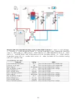
Connection of reserve boiler 

The  regulator  can  control  a  reserve  boiler 
(gas-  or  oil-),  eliminating  the  necessity  of 
enabling  or  disabling  this  boiler  manually. 
The  reserve  boiler  will  be  enabled  if  the 
temperature  of  the  pellet  boiler  drops,  and 
disabled  when  the  pellet  boiler  reaches  an 
appropriate  temperature.  Connection  to  a 
reserve boiler, e.g. oil-boiler one, should only 
be  made  by  a  qualified  fitter,  in  accordance 
with  the  technical  documentation  of  this 
boiler. 
The  reserve  boiler  should  be  connected  via 
relay to terminals 43-44 (Output H). 


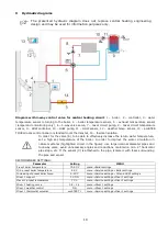
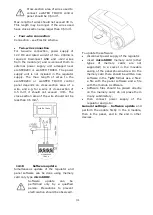
Model diagram of layout for connecting a  reserve 
boiler  to  the  regulator,  where:  1-  regulator,  2  – 
reserve  boiler  (gas-  or  oil-),  3  –  module  U3, 
consisting of relay RM 84-2012-35-1012 and base 
GZT80 RELPOL. 

 
In  a  standard  version,  the  regulator  is  not 
equipped with the U3 module.  


It  should  to  perform  assembly  and 
installation  of  the  module  by 
yourself,  in  conformity  with  the 
applicable standards. 

Set the temperatures of reserve boiler switch 
on/off: 
Service  settings 

  Boiler  settings 


Reserve  boiler 

    Reserve  boiler


Reserve boiler activation temp.  
Control  of  reserve  boiler  is  off  upon  setting 
this parameter at ,,0”. 
Then should set the support for output H for 
reserve boiler: 
Service  settings 

  Output  H  =  Reserve 

boiler 
Once  the  boiler  has  been  fired  up,  and  its 
temperature  has  exceeded  the  preset  value 
(e.g.  25

C),  regulator  switches  off  the 

reserve boiler and applies voltage 12V DC at 
output H, which causes release of  coil of U3 
module relay and opening its contacts. Once 
the  boiler  temperature  has  dropped  below 

Содержание ecoMAX860P TOUCH

Страница 1: ...AX920P1 T INSTRUCTION INSTALLATION AND OPERATING MANUAL ISSUE 1 0 APPLIES TO SOFTWARE MODULE A PANEL v01 XX XX v 01 XX XX ecoSTER TOUCH ecoNET300 functions available in the additional module B room pa...

Страница 2: ......

Страница 3: ...OF TEMPERATURE SENSORS 26 12 7 CONNECTING WEATHER SENSOR 26 12 8 CONNECTING EXHAUST SENSOR 26 12 9 CHECKING TEMPERATURE SENSORS 27 12 10 CONNECTION OF MIXERS ROOM THERMOSTAT 27 12 11 CONNECTION OF BOI...

Страница 4: ...for boiler manufacturers Before applying the regulator a boiler manufacturer should check if the regulator s mating with the given boiler type is proper and whether it can cause danger The regulator...

Страница 5: ...supplement for the boiler manual In particular except for this manual the boiler manual should also be observed The regulator manual is divided into two parts for user and fitter Yet both parts contai...

Страница 6: ...6...

Страница 7: ...INSTRUCTION MANUAL ecoMAX 860P TOUCH...

Страница 8: ...libration Scheduled On Reduction value Schedule HUW settings HUW preset temperature HUW pump mode Off Priority No priority HUW container hysteresis HUW disinfection Schedule HUW On No Yes Reduction va...

Страница 9: ...meaning of the symbols opening of room thermostat contacts preset room temperature has been reached of preset boiler temperature for active time intervals increase of preset boiler temperature for the...

Страница 10: ...l After three unsuccessful attempts an alarm Failed firing up attempt is reported In such case the boiler operation is halted Boiler operation cannot be continued automatically service crew must inter...

Страница 11: ...e boiler temperature decreases and the boiler automatically switches to OPERATION mode For the setting Supervision time 0 the regulator skips the SUPERVISION mode and enters the BURNING OFF mode When...

Страница 12: ...function can be activated automatically with the Auto parameter including settings for SUMMER mode act temperature SUMMER mode deact temperature 8 15 Disinfection HUW container The regulator has a fun...

Страница 13: ...ot recommended to use both options at the same time Automatic correction of room temperature is carried out in accordance with the following formula Correction Preset room temperature measured room te...

Страница 14: ...r boiler heating circuits HUW container and circulation pump operation The intervals can be used to define time periods at which lower preset temperature may be set e g for a night time or when the us...

Страница 15: ...tion No additional fuel level sensors are required Calibration To perform calibration fill the fuel tank to the level corresponding to its full load and set the parameter Boiler settings Fuel Level Fu...

Страница 16: ...In Touch version in the menu bar at the bottom of the screen there is a button Upon activation of this key a quick selection menu appears To add new item to this menu hold respective icon pressed in...

Страница 17: ...INSTALLATION AND SERVICE SETTINGS ecoMAX 860P TOUCH...

Страница 18: ...ature of the boiler In order to improve the water circulation in natural systems highlighted circuit in the figure use large nominal diameter pipes and four way valve avoid unnecessary angles and redu...

Страница 19: ...u Service settings CH and HUW settings CH pump boiler pump YES menu Service settings CH and HUW settings Mixer 1 support CH activated menu Service settings Mixer 1 control Max preset temp of mixer 1 7...

Страница 20: ...Loading start temperature 50 C menu Service settings Buffer settings Loading stop temperature 75 C menu Service settings Buffer settings Mixer 1 support CH activated menu Service settings Mixer 1 sett...

Страница 21: ...12 1 Environmental conditions Due to fire risk it is forbidden to use the controller in proximity of explosive gases or dust Moreover the controller cannot be used in conditions of water steam condens...

Страница 22: ...in accordance with applicable regulations Caution After the regulator is turned off using the keyboard dangerous voltage can occur on the terminals Before starting any assembly works you must disconn...

Страница 23: ...If there is a necessity to strip cable insulation more than 60mm cable leads should be fasten together or with other leads near the connector in order to prevent contact with unsafe parts in the case...

Страница 24: ...pper buffer temp sensor type CT4 BL lower buffer temp sensor type CT4 WS weather temp sensor type CT6 P FT exhaust temp sensor type CTS2 TR universal boiler thermostat NO NC H output to control the si...

Страница 25: ...l sensor used with the BU feeder RM3 mixer 3 room thermostat RM4 mixer 4 room thermostat H2 voltage output for controlling the reserve boiler or alarm signalling or HUW circulation pump RELAY relay L...

Страница 26: ...f sensors and hot parts of the boiler and the heating installation Wires of sensors are resistant to temperature not exceeding 100 C 12 7 Connecting weather sensor he regulator cooperates solely with...

Страница 27: ...1000 3 25 1096 9 1097 3 1097 7 50 1193 4 1194 0 1194 6 100 1384 2 1385 0 1385 8 125 1478 5 1479 4 1480 3 150 1572 0 1573 1 1574 2 CT2S PT1000 exhaust Temp C Min Nom Max 0 999 7 1000 0 1000 3 25 1096...

Страница 28: ...e system caused by a pump stop The pump interlock by opening the contacts of the room thermostat may be activated only upon making sure the boiler will not be overheated 12 12 Connection of reserve bo...

Страница 29: ...to ensure free gravitational flow of water in the boiler circuit active cross section of switching valve 4 has to be larger than or equal to cross section of boiler circuit pipes Use pipes of large c...

Страница 30: ...supply check whether wires to mixer closing and opening are not interchanged To do this enter MENU Manual control and open the mixer by selecting Mix1 Open ON When opening the servo the temperature on...

Страница 31: ...cross section area of the wire should not be less than 0 5 mm2 12 18 Software update Simultaneous update of the regulator and panel software can be done using memory card only type microSDHC Software...

Страница 32: ...Lack of fuel detection method Exhaust only Water and exhaust Boiler hysteresis Purge operation supervision Purge interval supervision Return protection Return protection 4D Return hysteresis Min retu...

Страница 33: ...o adequate sensor or additional module is connected or the parameter is hidden Manufacturer menu Reset counters Reset alarms Exhaust alarm temperature Flame return feed time Flame return detection del...

Страница 34: ...cycle time OPERATION feed time feeder standstill time Feeder efficiency Efficiency of the fuel feeder in kg h Entered a measured amount of fuel in constant feed feeder working constantly The parameter...

Страница 35: ...for exceeding the maximum feeder temperature is displayed When this temperature is exceeded the feeder is engaged for a predefined time with a several minute pause If the temperature drops the regula...

Страница 36: ...e boiler Determines pellet boiler temperature below which reserve boiler is activated i e gas boiler Setting 0 value causes deactivation of reserve boiler control and switching joint number 43 44 on a...

Страница 37: ...min The circulation pump is operating in cycles for the time of circulation operation time recommended setting is between 60 and 120s Circulation pump operation time CH pump working mode Available opt...

Страница 38: ...g it should be set for the value below 45 50 C or even lower when the thermal resistance of this floor is lower Attention setting too lower value of this parameter can lead to unnecessary shut down of...

Страница 39: ...r Alarms when an alarm occurs output 43 44 is activated Alarm exhaust temperature Exhaust temperature above which the alarm will be activated Available only in the GRATE mode Flame retract feeding tim...

Страница 40: ...cancelled only after the feeder temperature decreases by restarting the regulator The function of protection against flame recession is inoperative if the feeder sensor is disconnected or damaged The...

Страница 41: ...ss the Reset button 15 10 Max exhaust temperature exceeded Sensor damage danger This alarm occurs only when using the GRATE and exceeding the maximum exhaust temperature The fan is turned off Its aim...

Страница 42: ...parameter can be found in Service settings Burner settings If the parameter Additional feeder operation time is set to 0 this work additional feeder is turns off 17 REPLACEMENT OF PARTS AND COMPONENT...

Страница 43: ......

Страница 44: ...19 Ignatki 16 001 Kleosin Poland phone 48 85 749 70 00 fax 48 85 749 70 14 plum plum pl www plumelectronics eu Jacek Kucharewicz ul Sikorskiego 66 16 100 Sok ka Poland tel 48 85 711 94 54 www metalfac...

Отзывы: