4I33 2
HARDWARE CONFIGURATION
GENERAL
Hardware setup jumper positions assume that the 4I33 card is oriented in an
upright position, that is, with the PC/104 connectors towards the person doing the
configuration.
LOCAL TRANSCEIVER POWER
The on card BNC transceiver power can be enabled or disabled via jumper
block W2. BNC Tranceiver power should only be disabled when an external BNC
transceiver such as MESAs MAU is used. Make sure that local transceiver power is
disabled if a MESA MAU is used. If left enabled when a MAU is used, an
overload will occur and power supply damage may result!
It is not necessary to disable transceiver power to save current consumption in
10BaseT mode, since the Ethernet chip will automatically disable the DC-DC converter
when the 10BaseT interface is used.
Moving W2 to the UP position enables local transceiver power, moving W2 to
the DOWN position disables local transceiver power.
BNC TERMINATION
The local BNC port can be terminated on card if desired. This can be useful to
avoid the space used by a BNC terminator where space is at a premium. It must not
be enabled unless the 4I33 card is at one end of the BNC cable run. JumperW3 is set
to the UP position to enable termination, and the DOWN position to disable
termination.
SERIAL PORT LOCATION
The optional on-card serial port can be located at 4 different I/O addresses,
COM3, COM4,COM5, or COM6. These locations are determined by a PAL and can be
changed if needed.. Jumpers W4 and W5 (labeled SLOC on card) set the serial port
locations as follows:
W4
W5
LOCATION
DOWN
DOWN
COM3 = 3E8H
DOWN
UP
COM4 = 2E8H
UP
DOWN
COM5 = 100H
UP
UP
COM6 = 108H
Содержание 4I33
Страница 1: ...4I33 MANUAL PRELIMINARY V1 0...
Страница 2: ...page intentionally not blank...
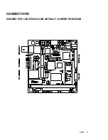
Страница 8: ...4I33 5 CONNECTORS CONNECTOR LOCATIONS AND DEFAULT JUMPER POSITIONS...

