G715
D
May 05
10
transformer input
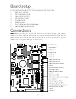
Can accept 12 or 24 V ac, max 100 VA, max 10 A. Use the transformer supplied.
battery input
A 12V 1.2 Ah sealed lead-acid back-up battery is recommended, and should result in
sufficient capacity for at least five operations in the first 24 hours of any mains failure.
motor (MOT) output
If the motor direction is reversed, swap the polarity of the connection wires.
flashing warning lamp output (LAMP)
The outputs are set up for a 2 W flashing lamp, at either 12 or 24 V dc, depending on the
board’s supply voltage. The board supplies power to the lamp, but it is a continuous supply,
so the lamp must have a flashing circuit built in.
The output supplies power to the lamp from 1 second prior to opening, until fully open; and
from two seconds prior to closing, until fully closed.
If the board is running only from battery backup, then the lamp will only flash for the first
four seconds of operation.
courtesy lamp (EXT. LAMP) / electric lock (EL. LOCK)
module output
To connect an electric lock or a courtesy lamp, it is necessary to fit an optional expansion
module. Only one module can be fitted. This must be connected with the three wires
arranged as: red to terminal 3 (VA); grey to terminal 8 (EL); black to terminal 7 (ground).
The ELU Electric Lock Unit module can accept a lock rated at up to 12V 15W.
The LCU Lamp Control Unit module can accept a lamp rated at up to 12V 15W.
tx photocell power output (TXF), photocell signal input
(PHO)
Photocells should have NC (normally closed) contacts when there is no obstruction. Fit a
jumper wire between the signal input terminal and ground if no photocells are fitted.
The maximum total accessory power load allowed is 150 mA. The combined consumption
on the TXF and VA terminals must not exceed this limit. Photocells are part of this total
load.
NOTE 1
If the TEST jumper is fitted, the unit performs a function test on the photocells
before each operation. This adds a 200ms delay before every operation. The transmitting
photocell must be powered from the TXF output. Photocells must have NO (normally open)
contacts when the power is off.
NOTE 2
If the PAU trimmer is set to fully anticlockwise and the photocell beam has been
interrupted, then the gate will close 1 second after the beam is cleared.
NOTE 3
The default behaviour is to react immediately when the beam is interrupted.
Professional Setup Step 12 allows this to be changed. The gate can be made to stop in
response to an obstruction, and then only react after the obstruction is removed.
Содержание G715D
Страница 13: ...13...
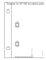
Страница 14: ...G715D May 05 Template for G715D foundation plate M8 8 8 M8 This edge to face the rack gate and pinion...
Страница 16: ...G715D May 05 16...


