Meriam MFT 4000 Скачать руководство пользователя страница 62

 57

1151:  Pump 8:

  Line 1 displays the model and tag number or service description of the device connected 

to the MFT.  The model of the device is fixed and cannot be changed by the user.   
 

Device Config: 

 Line 2 is dedicated to accessing the HART configuration menus. See the Device Setup 

section below for further information. 

PV: 

 Displays the current primary variable’s value as reported by the digital side of the HART device. 


AO:  

Displays the current analog output value as reported by the digital side of the HART device. 


LRV: 

Displays the Lower Range Value of the transmitter corresponding with a 4 mA analog output. 


URV: 

Displays the Upper Range Value of the transmitter corresponding with a 20 mA analog output. 


% of Range:  

Reflects the primary variable reported as a percent of full-scale range. 


AO Fixed: 

 Line 9 is a message line used to display general messages including but not limited to the state 

of HART device output, errors, or warnings. 

This line will be blank if no messages or warnings are 

active.


Device Configuration 

From the 

HART Device Online Screen

 move the cursor to 

Device Config

 and press the 

Select 

soft key. 

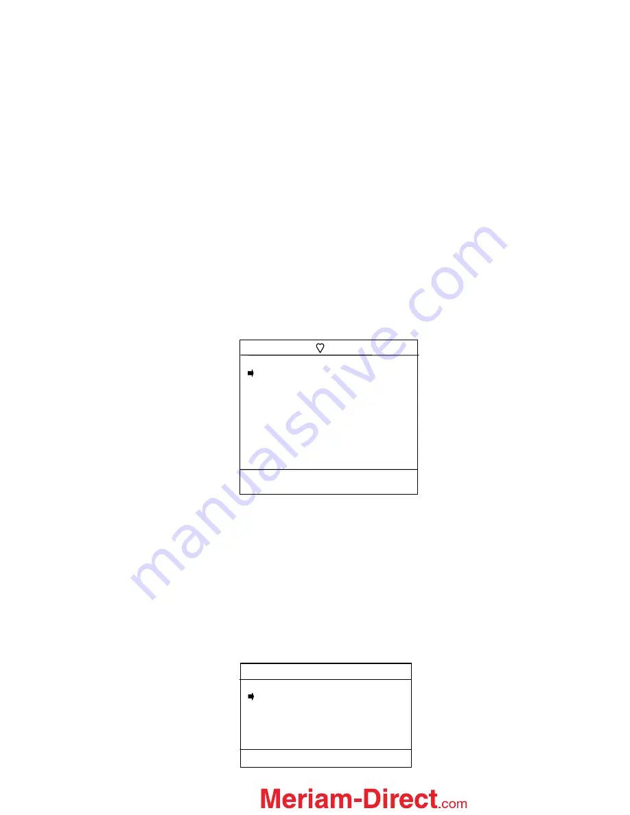
The menu screen below allows the user to select a number of tasks. These include changing editable 
parameters, re-ranging the device, calibration, and device diagnostics. 


Process Variables 

The 

Process Variables

 option allows the user to review information concerning the process variables (such 

as pressure, current, etc...) as reported by the transmitter. 
To enter the 

Process Variables 

option, use the 

Up 

or 

Down

 soft key to move the selection arrow to 

Process


Variables

, and then press the 

Select

 soft key.  The MFT will then display the process variables 

being sent by the HART device. 
Press 

Back 

to return to the 

Config Menu

 screen. 


Sensor 

This option allows the user to manage and configure sensor range and perform trim functions. From the 

Device Config

 screen scroll the cursor to 

Sensor 

and press the 

Select

 soft key.  

The following screen will appear: 


Sensor Menu                 
1151: Pump 8     


 Rerange 

   Signal Conditioning 
   Pressure Trim 
 
 
 Up      Down       Select      Back

Config Menu  
1151: Pump 8     


 Process Variables 

   Sensor 
   Analog Trim 
   Basic Info 
   Hart Output 
   Diagnostics 
   Save/Send 
   Review/ Edit 
 
Up      Down       Select       Back 

Device Config Screen

1.888.475.5235

[email protected]

Содержание MFT 4000

Страница 1: ...4000 Calibrator MFT 4005 Calibrator with HART Trims MFT 4010 Calibrator with HART Communications USER S MANUAL File No MFT 4000 440 6 Firmware v 4 0 greater Nov 2006 1 888 475 5235 info Meriam Direct...

Страница 2: ...hone at 216 281 1100 or by e mail at meriam meriam com HART is a registered trademark of the HART Communication Foundation Important information on the product is contained in this manual Read this ma...

Страница 3: ...gital Poll 7 EJA EJX Accuracy Utility Yokogawa 8 Lockouts 9 Master Lockout 9 PV Prompt 9 Unlocking the MFT 9 Changing the Lockout Code 9 Clock Timers 10 Others 10 Model Info 10 Battery Type Select for...

Страница 4: ...Sensor Trim 29 View Results 30 Clear Cal Memory 31 Documenting Calibration Results 32 Entering Calibration Documentation Mode 33 Manual Calibration Procedures and Documentation 34 Local Indicators or...

Страница 5: ...ART Communications 73 Documenting HART Configurations with Meriam DMS 73 Download Site Information DOFs Firmware Utilities 73 Who has access to the Download Site 73 PC Requirements for Download Operat...

Страница 6: ...eys dual function keys and soft keys Single function keys control a dedicated MFT function Dual function keys through the use of the Function key control two separate functions Soft key functions chan...

Страница 7: ...r2 The S2 Units key changes the engineering units for the module in sensor bay 2 The Function key must be active before the units can be changed When numeric entry is anticipated by the MFT this key c...

Страница 8: ...oft key functions Pressing the MFT s FUNCTION key changes the display from one grid to another allowing text messages to be developed using all three grids when needed When using any character grid pr...

Страница 9: ...display confirming this mode is active The soft key definitions in this mode are directed toward measurement and information functions Header line Symbol Key see location at right heart symbol indicat...

Страница 10: ...aborted if more than 5 of full scale signal is being measured by any MFT sensor Absolute pressure modules cannot be zeroed until the applied pressure is less than 5 of full scale This prevents the acc...

Страница 11: ...and the date the unit was last calibrated Pressing Next consecutively scrolls through the remaining installed sensors then the electrical inputs and finally the MFT itself The MFT information provides...

Страница 12: ...options and select the desired damping Damping method selected here becomes the normal damping mode Units The Units menu line of the Measurements Menu Screen allows the user to scroll through and sel...

Страница 13: ...or None used for the calibration If a module is selected then the accuracy of the pressure module is used to determine overall error If None is selected then the design accuracy of the EJA EJX is calc...

Страница 14: ...ft keys to enter and store a 3 digit code If no Lockout code is active then using the Chng soft key to change the status to Enable will cause the unit to request a 3 digit lockout code of the user s c...

Страница 15: ...date and time will remain active Date time information is continuously powered by an internal 10 year life back up battery This battery is not serviceable by the user Other This menu option provides...

Страница 16: ...nsor lock far enough to clear the housing Once a sensor module is removed from a bay the display will clear that sensor s information from the display screen Note Modules should be removed or installe...

Страница 17: ...oor screw and reinsert the strap through the metal strap guide and re secure the Velcro Note Replace all six 6 AA batteries at once with alkaline or NiMH cells Do not mix alkaline or NiMH batteries wi...

Страница 18: ...e sensor range without sustaining damage xDN Differential Non Isolated Modules are capable of withstanding up to 2x the sensor range when pressurized on the high side only When pressure is applied to...

Страница 19: ...ere When calibrating a gauge pressure unit using an xGI sensor the connection is the same with the exception that the xGI sensor does not have an external vent to atmosphere In some cases the actual p...

Страница 20: ...ur if more than 15 PSI is applied to the high or low side of an xDN0020 or xDN0200 sensor through improper use of the equalizing manifold Additional DP Application Information In addition to reading g...

Страница 21: ...ations use a xAI sensor module These sensor modules have an internal absolute zero reference Simply connect the pressure or vacuum source to the single port on the module The following diagram shows t...

Страница 22: ...e MFT is connected in series with the loop using standard banana jacks Important Use the transmitter s working terminals to measure mA not the TEST terminals found on some transmitters Do not use digi...

Страница 23: ...he Rcal soft key This will access the Field Recal Setup screen Field Recalibration Setup Screen Module Select to choose which sensor module S1 S2 S3 or mA V I or V meter to calibrate Units Allows the...

Страница 24: ...menu Make sure your pressure source and calibration standard are properly connected to the sensor module under test Connections must be leak free The first recalibration target pressure is normally ze...

Страница 25: ...n point you wish to customize Abort Pressing the Abort key will immediately cancel all calibration value changes made to that point retain the previous calibration and return to the Measure Mode Next...

Страница 26: ...l ejection of batteries See the Installation and Removal of Batteries section of this manual for more details WARNING Serious injury or death may result from explosions Do not make connection to the D...

Страница 27: ...shrouded standard banana jacks 3 4 center for 50 mA volts measurements HART loop connections are also standard banana jacks For Intrinsically Safe MFT models consult the Hazardous Area Use section of...

Страница 28: ...n and press Save to make the change Device Out Conventional mA PV User Entry This option allows the user to select between the calibration of a HART device non HART or device requiring User Entry loca...

Страница 29: ...t the Cal Type menu option to change the type of calibration desired The following screen is shown P Pressure transmitter calibration T C T C temperature transmitter calibration RTD RTD temperature tr...

Страница 30: ...selected for I P converter calibrations and some special applications Press the Back soft key if you choose not to make any changes The MFT will then return to the Calibrate key main menu screen Sele...

Страница 31: ...e screen press the Calibrate key and move the selection arrow to Quick Cal menu option Press the Select soft key The following screen will appear Comparison of AO to the MFTs V I measurement of loop c...

Страница 32: ...or control system such as a chart recorder PLC or DCS in manual mode Press the OK soft key to continue or press the Abort soft key to return to the Hart Smart Trim Screen The following screen will app...

Страница 33: ...ceiving device or control system such as a chart recorder PLC or DCS in manual mode Press the OK soft key to continue or press the Abort soft key to return to the Hart Smart Trim Screen The MFT will n...

Страница 34: ...Remove Pressure This notice reminds the user to release the pressure applied Press OK to continue The screen will now prompt Put Loop back online This notice reminds the user to reconnect the device u...

Страница 35: ...continue Press the Back soft key to return to the Hart Smart Trim Screen main menu screen Pressing Back again will return the MFT to the Calibration key main menu screen View Results Allows users to v...

Страница 36: ...aved point for the active tag number Use the Back soft key to go back to the prior screen Clear Cal Memory To clear all calibration procedure result files Select the Clear Cal Memory menu option under...

Страница 37: ...d procedures are set up in the Meriam Device Management System software and assigned to device tag numbers there The procedures are then downloaded to the MFT Conventional and HART transmitters can bo...

Страница 38: ...cal indication local indicators or Fieldbus device readings The following screen will appear Cal Type This option allows the user to select and set up the type of calibration desired Cal Type menu pro...

Страница 39: ...der test so select the Sx location for the RIO4000 measure and simulation module Review the second page of Manual Calibration Input information by selecting the More menu option on the first page This...

Страница 40: ...of the documenting session If the MFT needs to provide simulation of an input signal to the device under test the Meas Sim line will have been pointed to a simulation module such as the RIO4000 TIO01...

Страница 41: ...input signal Repeat as needed to complete the calibration procedure The As found portion of the calibration documenting session will end automatically If the MFT needs to provide simulation of an inp...

Страница 42: ...adjustments for zero and span As left Reactivates the documentation feature to save As left data View Results Allows user to view saved calibration results from As found or As left work Returns to Cal...

Страница 43: ...the MFT s keypad to enter the local indicator reading or the output reading from the fieldbus device Or use Inc and Dec Soft keys enter the first number of the value being input Press the soft key to...

Страница 44: ...for calibration activities See the DMS User s Manual for more details To start a From PC Stored Procedure Calibration press the MFTs Calibrate key set up the MFT for From PC Procedure using the Proce...

Страница 45: ...gnal as indicated by Sx to more closely agree with the Apply value shown The MFT will not save a set of data if the Sx value varies from the Apply value by more than the percentage selected in the DMS...

Страница 46: ...of the device under test after trim operations are complete The From PC Stored Procedure Calibration Documentation Screen appears again to guide the user through the necessary procedure points as bef...

Страница 47: ...mperature or Switch type documenting calibrating sessions and are convenient for repetitive calibration documentations of similar device setups To enter Template procedures from Measure Mode press the...

Страница 48: ...the loop to simulate a transmitter output to the loop loop is externally powered for this test with greater than 20 mA available on the loop For HART devices the MFT 4010 sends HART commands to fix t...

Страница 49: ...numeric entry system of the MFT to enter the proper tag and press the Done soft key Answer Yes to save the loop tag confirm the information on Begin Calibration Setup Screen is correct and then Select...

Страница 50: ...ft above At this point the user determines the loop current received at the control room or the value read at the receiving device involved and enters the value into the MFT by selecting the Entry sof...

Страница 51: ...wnload loop calibration procedures to a documenting MFT for use in the field For conventional devices the VMA0055 module is used to simulate a transmitter on the loop to be tested For HART devices the...

Страница 52: ...tails Example Wet bulb temperature switch test Install a VMA0055 module in bay location S1 of the MFT Install an RIO4000 module in bay location S3 of the MFT Place the wet bulb probe of the temperatur...

Страница 53: ...st detail Be sure to consult the information on the More menu since it allows the user to specify a LRV and URV for the test This is especially useful for switch tests using a simulation module since...

Страница 54: ...ection contact closure on Increase or Decrease Test Reset Pt testing reset point is optional Ramp Minutes time for ramp when simulating RTD or T C Start Delay optional start delay in minutes Contact F...

Страница 55: ...procedures to a documenting MFT for use in the field The VMA0055 module is normally used to wet the switch circuit to be tested although external wetting by a VDC source of 50 VDC or less is also sup...

Страница 56: ...m HART pressure and temperature transmitters Connections to the device under test are the same as those made for the MFT 4010 Other differences include the following When the Quick Menu key is selecte...

Страница 57: ...ommon Practice Commands are used for calibration and maintenance functions that are common to many devices An example of this would be to trim or adjust the analog output Third Device Specific Command...

Страница 58: ...options launch Multidrop poll by selecting the Multi soft key retry Device 0 communication after re checking physical connections to the device by the selecting Retry soft key or to Exit to Offline m...

Страница 59: ...0 15 Digital Polling is a special feature accessible through the MFT s Main navigation screen and the Cfg soft key Press the Cfg soft key and then select the 2 Applications menu option Select the 1 D...

Страница 60: ...th the factory lockout code of 321 With the default set to disable the MFT will only save the PV parameters for the current PV assignment of the multivariable device To enable all multivariable device...

Страница 61: ...mber required The menus prompt the user to make the necessary configuration selections tag the file for later retrieval and use and edit configuration lines as required This function can be locked out...

Страница 62: ...the HART Device Online Screen move the cursor to Device Config and press the Select soft key The menu screen below allows the user to select a number of tasks These include changing editable paramete...

Страница 63: ...t key to move to the next character Press the Done soft key when the changes are complete A prompt will appear Save new data Press the Yes soft key to accept the changes Pressing the No soft key will...

Страница 64: ...pond to zero pressure make sure HART device is vented to atmosphere The screen will display the prompt Put Loop back online This notice reminds the user to return the device to service Press the OK so...

Страница 65: ...n screen Use the Edit soft key to make changes Press Back to return to the Signal Conditioning main menu screen After pressing Edit the screen will show the current setting for the Transfer Function U...

Страница 66: ...us primary variable settings Move the cursor to Pressure Trim and press the Select soft key The following menu screen will appear Zero Trim This option allows the user to trim the zero pressure report...

Страница 67: ...isplay the prompt Remove Pressure This notice reminds the user to release the pressure applied Press OK to continue The screen will display the prompt Put Loop back online This notice reminds the user...

Страница 68: ...he following screen will appear D A Trim This option allows the user to trim the analog output 4mA 20mA of the connected HART device A multimeter will be needed to use this trim feature operating out...

Страница 69: ...r the loop current value can be obtained by dividing the voltage by the resistor value Scaled D A Trim allows the user to enter this voltage directly instead of having to convert it into the actual cu...

Страница 70: ...er value read from the multimeter display Use the Numeric Grid and soft keys to enter this value Press Done when finished Select No if the meter does not read the correct scale value for 20 mA output...

Страница 71: ...ill appear in the message area shown above This area will be blank if no messages are issued by the HART device To set output automatically to desired value of 4 8 12 16 20mA select the corresponding...

Страница 72: ...key to change current settings Use the Alphanumeric Grids options see Alphanumeric Entry Section in this manual and soft keys to select desired characters Press the Select key to enter alphanumeric in...

Страница 73: ...ails HART OUTPUT This option allows the user to configure the HART communications protocol options It also provides information about the HART device ID and Burst Com number To enter the Hart Output o...

Страница 74: ...w data should be saved Pressing Yes puts the MFT into the selected burst mode and returns the MFT to the Hart Output main menu screen Selecting No leaves the device in the original As found burst mode...

Страница 75: ...llows the user to save the configuration by two ways 1 Only the PV parameters OR 2 The parameters of all variables primary secondary tertiary etc by sequentially changing each variable to PV and savin...

Страница 76: ...o a specific HART menu This is a time saving feature that allows the user to skip entire blocks of standard HART menus and jump directly to a frequently used function Quick Menu titles are the same as...

Страница 77: ...on To optimize DOF flash memory it is necessary to delete all DOFs and then reload them all in one session Connect the MFT to a host PC that has DPC Manager installed see the DPC Manager Utility secti...

Страница 78: ...he latest Device Specific DOF files to your MFT DOCUMENTING HART CONFIGURATIONS All MFT 4010 models are able to save and send HART device configuration files They are also able to upload saved configu...

Страница 79: ...e downloaded from the detailed description page of each DOF or firmware file listed Each column can be sorted to assist searches of the release database Also available on this screen are the navigatio...

Страница 80: ...ovided by the Meriam Repair Department when you call fax or e mail your information An RMA number must accompany all incoming packages to insure proper tracking processing and repair work To assist us...

Страница 81: ...es Hg inches Hg with 0 C ref temp oz in2 Temperature F C R K Others based on module option CONFIGURABLE DISPLAY user configured for one to four measurements AUTO SHUT OFF occurs after user selected pe...

Страница 82: ...damping rate setting HOLD toggle function freezes display ZERO simultaneous re zeroing of all installed modules CONTRAST direct adjustment of display contrast FIELD RECERTIFICATION sensor modules and...

Страница 83: ...T Trims Base unit for use with sensor modules plus HART trims for pressure and temperature transmitters MFT 4010 Multi Function Tester with HART Communications Base unit for use with sensor modules pl...

Страница 84: ...ge Pending 06 Italian language Pending 07 Japanese language Pending 4010 11 1 01 0 01 0 01 Full Model ID MFT4010 11 1 01 0 01 0 01 Calibrator HART Communicator Meriam Standard Documenting Intrinsic Sa...

Страница 85: ...nn 1 m cable t c wire Kit 1 for B K R S mini t c conn 1 m cable mV meas sim cable assbly mini t c conn 1 m cable VMA0055 Starter Kit for VMA0055 module V I meas sim Universal RIO4000 Starter Kit for R...

Страница 86: ...PSI max P N B34700 Vacuum pump with variator 600 mm Hg max P N A34386 low pressure fittings and tubing kit vacuum to 150 PSI connectors tees NPT adapters P N A900020 90502 high pressure fittings and h...

Страница 87: ...t Mode 1 1 Install the TIO0110 module in any MFT bay location and turn on the MFT If no t c is connected to the MFT the Sx line will indicate T C open If a t c is connected a temperature will be shown...

Страница 88: ...procedure 2 1 The Start menu begins a TC or mV simulation When Start is selected with the Select soft key a numeric entry screen appears to facilitate the entry of the desired simulation temperature v...

Страница 89: ...2 5 7 Select Start delay to select a start delay from None to 5 minutes 3 0 User Re Calibrate This menu option accesses the controls used for re calibration of the TIO0110 module using local standard...

Страница 90: ...ltage range 110 000 mV dc Temperature Storage 40 F to 140 F 40 C to 60 C Operating 23 F to 122 F 5 C to 50 C Connector Measure Simulate T standard mini t c connector with t c wire Source mV standard m...

Страница 91: ...sure 55 000 V dc 100 000 mA dc 1 0 Measurement Applications The VMA module will measure voltage and current to upper values that exceed the MFT base unit s metering capabilities 1 1 Use Volts and Com...

Страница 92: ...from the MFT Measure Mode by pressing the following keys Press the More Soft Key two times Press the Pon Soft Key to turn VMA power supply on The SX sensor location depending which bay the VMA is loc...

Страница 93: ...rst then Next changes to bay S2 etc 3 4 Press the Setup soft key option for the VMA module to display the VMA Main Setup Display VMA Main Setup Display Vma Setup Current Settings Start Mode mA Source...

Страница 94: ...lay for use in applications requiring both sourcing and measurement The IV line can be changed at this display from V to mA to off by using the MFTs Function and Units mA V keys as usual see the MFT U...

Страница 95: ...ircuit Voltage 24 VDC Output Drive 15 VDC minimum 24 mA Resistive load Volts dc V dc Measure Mode V dc Source Regulated Mode Resolution 1 100 000 counts 001 mV 001 V 1 1 000 000 Ranges 500 mV 1 2 4 8...

Страница 96: ...CSA C22 2 No 157 CAN CSA C22 2 No 1010 1 92 UL 913 Fifth Edition Rev 2 21 97 for Class I Division I Groups A B C D Hazardous Areas Restrictions apply see the Intrinsically Safe Control Document in App...

Страница 97: ...Otherwise select Next soft key to select the correct bay location From this window select the Setup soft key to start the user interface for simulation mode measure mode Rcal Mode 1 0 Simulation Mode...

Страница 98: ...There can be different configurations however these examples illustrate the corresponding RIO4000 connection required to perform RTD Simulation for 2 3 and 4 Wire RTD s RIO Setup Settings Functions Ch...

Страница 99: ...Units is used to select the temperature unit for the simulation C F K and R are the available The user can also select ohms if desired 1 2 3 Step Value is a user entered value that can be used to inc...

Страница 100: ...ng Configurations The module has a 6 pin male connector that plugs into a 6 pin female connector of the Measure cable by manufacturer Pt 100 RTDs are available complete with plug connector Rs resistor...

Страница 101: ...000 resistor na na 825 Precision cal resistor na Based on the Rs value connected between pins 1 and 2 the corresponding RTD Type look up table is utilized Plug connectors are available for customers t...

Страница 102: ...inals that are the same color Connect the two Red clips to the wires terminals of the same color Connect the two White clips to the remaining wire terminal 4 wire RTDs 4 wire RTDs have two wires termi...

Страница 103: ...2 5 Move the right arrow to the Select New RTD Type option and press the Select soft key The following will be displayed Measure S1 No probe S2 0 000 inW20C S3 0 00 PSIG IV 0 000 mA Zero Mn Mx Damp M...

Страница 104: ...rature reading the user can also press the Back soft key or press Measure Mode key 3 0 Rcal Field Recalibration The RIO4000 module can be recalibrated re certified using appropriate local standards an...

Страница 105: ...ated for 10 ppm total tolerance at most to replicate the original factory accuracy Selecting the Module Only option and connecting a 100 precision resistor causes the following display to appear Cal R...

Страница 106: ...be recalibration screen shown above provides the following information Cal Point target calibration temperature expressed in percent of the specified range The default Calibration Range is 20 C to 80...

Страница 107: ...tions used on the Module Probe recalibration type Adj allows the user to redefine the recalibration target points For example if the first desired calibration point is a value other than 20 C apply th...

Страница 108: ...for general purpose measurements on installed RTDs Simulate resistance User Cable with connector and two alligator clips Power supplied from MFT simulate source mode only Units F C R K ohms Weight 3 o...

Страница 109: ...2 200 to 0 0 2 0 5 0 to 400 0 6 0 4 400 to 630 0 8 0 6 Pt 500 385 392 200 to 0 0 2 0 4 0 to 400 0 3 0 5 400 to 630 0 4 0 6 Pt 500 391 200 to 0 0 2 0 5 0 to 400 0 4 0 4 400 to 630 0 5 0 6 Pt 1000 385 2...

Страница 110: ...105 Intrinsic Safety Document Uncontrolled Multifunction Tester MFT 4000 Series For Controlled document see drawing sent with actual handheld 1 888 475 5235 info Meriam Direct com...

Страница 111: ...rim DAC Trim Loop Test Scaled DAC Trim Revisions HART Revision Device Revision Software Revision Final Assbly Number Basic Info Tag Date Descriptor Message Private Label Revisions HART Output Polling...

Страница 112: ...Vent Material Flange Type Remote Seal Isolator Material Flange Size Number of Remote Seals Remote Seal Fill Fluid Remote Seal Type HART Revision Device Revision Software Revision Final Assembly Number...

Страница 113: ...erial Flange Material Drain Vent Material Flange Type Remote Seal Isolator Material Flange Size Number of Remote Seals Remote Seal Fill Fluid Remote Seal Type Universal Revision Transmitter Revision S...

Страница 114: ...mote Universal Revision Transmitter Revision Software Tag Date Descriptor Message ASC Model Ext SW Mode Revisions Const Mats Device ID Polling Address Request Preambles Burst Mode Select Burst Command...

Отзывы: