


19
desired option. Use the
Save
soft key to choose that option. The display will then return to the main
recalibration set-up menu. If you choose not to make any changes to a selected parameter, the
Back
soft key
returns the display to the main recalibration set-up
menu without making any changes.
Repeat this procedure for each parameter that needs to be changed.
Procedure - Field Recalibration
Once all of the desired parameters and options have been set, scroll
Down
to
Start
on the main recalibration
menu and press the
Select
soft key. This takes you into the recalibration display.
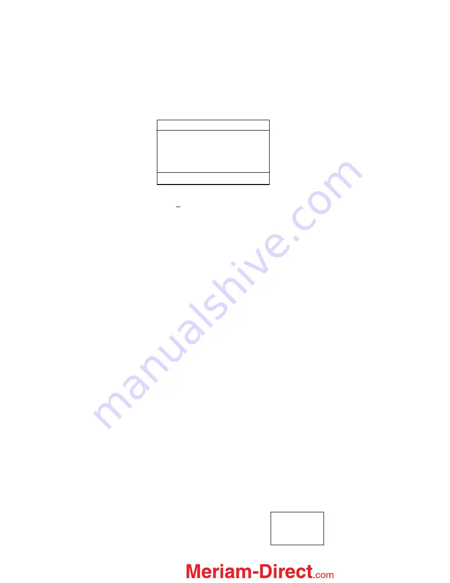
The recalibration screen shown above provides the following information:
Cal Point:
This is the target calibration point expressed as a percentage of the sensor module full scale
pressure.
The next line shows the sensor bay location or analog sensor being calibrated (S1, S2, S3, V, or mA). The
pressure applied by the user is also shown in the engineering units previously selected.
Error:
Is the percentage error between the applied calibration pressure and the recalibration target pressure for
the recalibration point (Apply value). + and – indicates whether the error is above or below the recalibration
target pressure (Apply value).
Apply:
This is the recalibration target pressure the MFT assigns based on the number of calibration points set
in the
recalibration set-up
menu.
Make sure your pressure source and calibration standard are properly connected to the sensor module under
test. Connections must be leak free. The first recalibration target pressure is normally zero, so the first point
should have all zeros. (As shown in example above—See section
Adj
for other options).
Adjust the pressure source until the pressure you are applying matches the
Apply
pressure & the
Error
percentage goes to zero.
If the error percentage is not zero, attempt to adjust the applied pressure until the unit reads zero. If zero error
can’t be achieved, a small error percentage within the accuracy of the unit under test or error within company
accuracy guidelines may be acceptable.
When the error % is within acceptable limits, press the
Next
soft key.
This moves the unit to the next calibration
point. Repeat the procedure outlined above. When the final recalibration point is set, press
Next
to store the
data.
After completion of the calibration process for 3, 5, or 9 points, the MFT will inquire if the cal data should be
saved. Select
Yes
to accept the recalibration data or
No
for other options.
If Yes was selected, the screen will verify the new calibration by displaying the date and module position
number. Press the
OK
soft key. The MFT then returns to the
Measure Mode.
Choosing
No
opens the
Cal Not Saved
screen with options:
Exit Cal
Restart Cal
Save Cal
Field Recal
Cal Point: 0%
Apply: 0.00
S1: 0.00 inW20C
Error: 0.000 %
Adj Abort Next
Back
Sample Field Recalibration Screen
(xDN Pressure Module)
1.888.475.5235