3. Loosen Allen screws on clutch sprocket and remove
sprocket from motor shaft.
4. Install new sprocket on motor shaft and tighten screws.
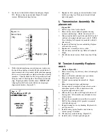
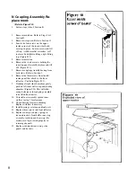
Check sprocket alignment (Figure #9).
5. Position chain on sprocket and slide motor to right to
remove slack. Tighten mounting bolts. Check chain
orientation.
6. Check chain tension (Figure #8) and adjust if necessary.
See Section G Number 5.
7. Replace right side panel.
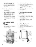
I Hubbed Sprocket Replacement:
(Refer to Figure 10)
1. Remove right side panel.
2. Loosen motor mounting bolts and slide motor to left.
3. Remove drive chain and loosen Allen screws on hub of
sprocket and slide off shaft.
4. Install new sprocket and align set screws with indents in
transmission shaft.
5. Replace drive chain and slide motor to right to tighten
(Figure #8) see Section G Number 5.
6. Replace right side panel.
J Bearing Replacement:
Coupling Bearing (Right Side)
1. See Section D, follow steps 1, 2 and 3.
2. Remove the two lock nuts holding bearing retainer and
remove retainer.
3. Remove old bearing.
9. Check sprocket alignment (Figure #9) and
adjust if necessary by moving clutch sprocket
on motor shaft. See Section G, Number 5.
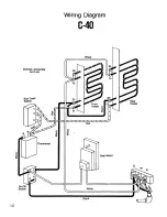
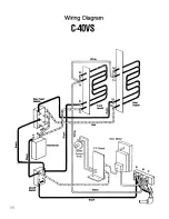
10. Reconnect wires (Refer to Wiring Diagram) and
replace side panel.
G Drive Chain Replacement:
(Refer to Figure 8 & 9)
1. Remove right side panel.
2. Loosen motor mounting bolts and slide motor to
left to loosen chain.
3. Lift off old chain and position new chain over
sprockets. Check orientation. (Figure #9).
4. Slide motor to right to remove chain slack and
tighten motor mounting bolts.
5. Check chain tension. (Figure #8). Too tight will
result in premature wear of chain, sprocket and
bearing and may bind drive components. Too
loose will result in chain slipping or falling off
sprockets.
H Clutch Sprocket Replace-
ment:
(Refer to Figure 8)
1. Remove right side panel.
2. Loosen motor mounting bolts and slide motor to
left and remove drive chain.
55

