


Electrical Description of EGM
Status September 2003 (EvoBus-Service / AFT)
Page: 51 of 83
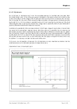
3.4.2.1
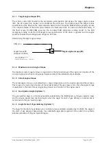
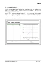
Principle of gas injector actuation
Actuation takes place according to the peak and hold principle with subsequent rapid current switch-off.
The actuation phases and the valve current curve are shown in the following illustration.
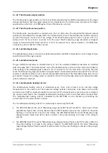
Actuation phases and current curve of gas injectors
Push phase
To achieve the pickup current of approx. 2 – 4 A (depending on valve type) as quickly as possible, the
battery voltage is connected to the valve with a high PWM pulse duty factor. The push time to be applied
is selected so that the desired, typical peak current is set. The actuation frequency is 10 kHz. The valve is
already opened before the end of the push phase.
Hold phase
After the push time expires, the system switches over to the holding mode with an actuation frequency of
5 kHz. The suitable selection of the pulse duty factor in this phase reduces the valve current to the
holding current following an e function. The reduced current during the hold phase both decreases the
losses in the valve and output stage, and also reduces the duration of the closing process in the switch-
off phase.
Switch-off phase
After the end of the desired gas injection period, the valve switch-off follows so that the magnetic energy
in the valve discharges against a 37 V switch-off pulse. The switch-off energy is dissipated by the
actuating transistor.
Pick-up
Holding current
Actuation phases of gas injectors
PWM 10kHz
Push
-Phase
PWM 5kHz
Hold-Phase
Switch-Off Phase
U(t)
I(t)
t
t
0V
24V
2 - 4 A
0A
(injector-dependent)
(injector-dependent)


