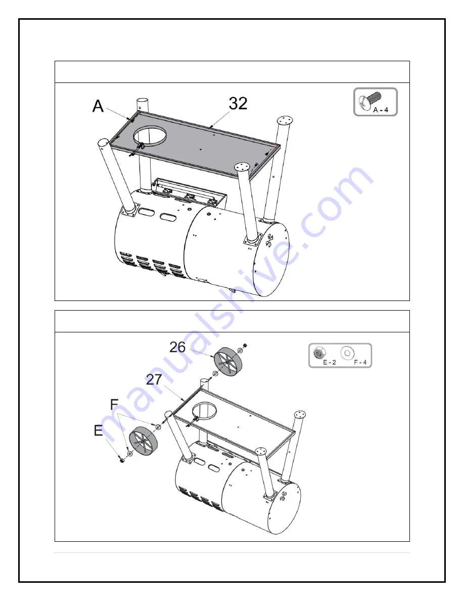
Member's Mark 980305021 Скачать руководство пользователя страница 16

16 | 

P a g e


Step 3

. Attach the 

Cart Base (32)

 to the cart legs using 4 pcs 

M6x12 Bolts (A). 

Do not 

fully tighten the bolts. 


Step 4

Attach the 

Wheel Axle (27)

 and the 

Wheels (26) 

to the cart assembly using 2 

pcs 

M10 Locking Nuts (E) 

and 4 pcs 

M10 Washers (F)


Содержание 980305021

Страница 1: ...Gas Combo Grill Item Number 980305021 980305488 Model Number GR2310803 MM 00 Customer Assistance spare replacement parts 1 888 837 1380 or Email customerservice rankam com THIS ASSEMBLY MANUAL CONTAIN...

Страница 2: ...Do not store or use gasoline or other flammable liquids or vapors in the vicinity of this or any other appliance 2 An LP cylinder not connected for use shall not be stored in the vicinity of this or a...

Страница 3: ...free work surface as this will avoid damaging parts during assembly The shipping box can provide an ideal work surface if none is available Use the components and hardware lists below to identify inve...

Страница 4: ...2 30 5cm diameter x 18 45 7cm tall with 20lb 9kg capacity maximum Type 1 outlet compatible with regulator or appliance Safety relief valve UL listed Overfill Protection Device OPD This OPD safety feat...

Страница 5: ...r only when the cylinder is resting on the cart base properly CAUTION When installing LP cylinders the pressure regulator and hose supplied by the manufacturer MUST be used with the appropriate cylind...

Страница 6: ...tank valve fully counterclockwise Use a soapy water solution to check all connections for leaks leak test before attempting to light the grill see P 32 33 If a leak is found turn the tank valve off a...

Страница 7: ...7 P a g e Package Contents...

Страница 8: ...Right Front Leg 1 11 Side Burner Grate 1 31 Right Rear Leg 1 12 Side Burner Assembly 1 32 Cart Base 1 13 Side Burner Frame 1 33 Cart Front Panel 1 14 Side Burner Control Panel 1 34 Tank Fixing Bolt 1...

Страница 9: ...No MET 3B0127 Qty 1 Component 4c Grill Body Heat Shield Part No MET 3B0128 Qty 1 Component 4d Grill Body Carry Over Part No MET 3B0129 Qty 1 Component 4e Grill Body Burner Part No GAS 3B0015 Qty 2 Com...

Страница 10: ...3B0133 Qty 1 Component 4n Grill Body Ignition Electrode Wire Part No ELE 3B0006 Qty 1 Component 4o Side Burner Ignition Wire Part No ELE 3B0008 Qty 1 Component 5 Smoke Stack Assembly Part No MET 3B013...

Страница 11: ...re Part No ELE 3B0007 Qty 1 Component 13 Side Burner Frame Part No MET 3B0142 Qty 1 Component 14 Side Burner Control Panel Part No MET 3B0143 Qty 1 Component 15 Control Knob Bezel Part No PLA 3B0009 Q...

Страница 12: ...Component 25 Cart Rack Support Part No MET 3B0152 Qty 1 Component 26 Wheel Part No MET 3B0153 Qty 2 Component 27 Wheel Axle Part No MET 3B0154 Qty 1 Component 28 Left Front Leg Part No MET 3B0155 Qty...

Страница 13: ...rt No HAR 3B0006 Qty 1 Component 35 Match Holder Part No MET 3B0161 Qty 1 Component 36 Side Burner Support Part No MET 3B0162 Qty 1 Component 37 Thermometer Part No THE 3B0004 Qty 2 Component 38 Therm...

Страница 14: ...E Qty 2 M10 Washer Item No F Qty 4 M4 Nut Item No G Qty 3 Hinge Pin Item No H Qty 2 Cotter Pin Item No I Qty 2 M6 Locking Nut Item No J Qty 1 Tanking Fixing Washer Item No K Qty 1 M4 Flat Head Bolt I...

Страница 15: ...recommended Step 1 Attach the Legs 28 29 30 31 to the Grill Body Assembly 4 using 16 pcs M6x12 Bolts A Do not fully tighten the bolts Step 2 Attach the Tank Fixing Bolt 34 to the Cart Base 32 using o...

Страница 16: ...ach the Cart Base 32 to the cart legs using 4 pcs M6x12 Bolts A Do not fully tighten the bolts Step 4 Attach the Wheel Axle 27 and the Wheels 26 to the cart assembly using 2 pcs M10 Locking Nuts E and...

Страница 17: ...17 P a g e Step 5 Attach the Cart Front Panel 33 to cart assembly using 4 pcs M6x12 Bolts A Step 6 Attach the Grease Cup Holders 18 to the grill body using 4 pcs M6x12 Bolts A...

Страница 18: ...18 P a g e Step 7 Attach the Cart Rack Support 25 to the cart assembly using 3 pcs M6x12 Bolts A Step 8 Attach the Cart Rack 24 to the cart assembly using 4 pcs M6x12 Bolts A...

Страница 19: ...Fully tighten all the bolts on the cart assembly Step 10 Remove the thermometer nuts from the Thermometers 37 Attach the Thermometers 37 and the Thermometer Bezels 38 to the lids using the removed nu...

Страница 20: ...P a g e Step 11 Attach the Lid Handles 8 to the lids using 8 pcs M6x12 Bolts A and 8 pcs M6 Nuts C Step 12 Attach the Side Burner Control Panel 14 to the Side Burner Frame 13 using 3 pcs M6x12 Bolts...

Страница 21: ...body and adjust to 3 16 clearance as shown Attach the side burner frame assembly to the grill body by using 6 pcs M6x12 Bolts A Step 14 Attach the valve to the Control Knob Bezel 15 and fix the side...

Страница 22: ...e Side Burner Assembly 12 to the side burner frame assembly using 3 pcs M4x10mm Bolts D and 3 pcs M4 Nuts G Step 16 Attach the Side Burner Lid 9 to the side burner frame assembly using 2 pcs Hinge Pin...

Страница 23: ...connector of the ignition wire to the terminal of the ignition electrode on the side burner assembly as shown below Insert the Control Knob 16 to the pin on the side burner valve Apply light pressure...

Страница 24: ...39 to the side burner lid using 2 pcs M5 Nuts M and 2 pcs M5 Washers N as shown below Step 20 Attach the Charcoal Tray Holders 7 to the charcoal grill body using 8 pcs M6x12 Bolts A Remind to install...

Страница 25: ...e Step 21 Attach the Smoke Stack Assembly 5 to the grill body using 4 pcs M6x12 Bolts A and 4 pcs M6 Nuts C Step 22 Attach the Air Vent 22 to the grill body using 1 pc M6x12 Bolt A and 1 pc M6 Lockin...

Страница 26: ...26 P a g e Step 23 Attach the Side Table 23 to the grill body using 4 pcs M6x12 Bolts A Step 24 Attach the Front Handle 19 to the grill body using 4 pcs M6x20 Bolts B and 4 pcs M6 Nuts C...

Страница 27: ...g e Step 25 Slide the Grease Cup 17 into the holding bracket at the bottom of the grill body Be sure the handle is facing outward Step 26 Place the Flame Tamers 3 and Charcoal Tray 6 on the grill as...

Страница 28: ...28 P a g e Step 27 Place the Warming Racks 1 Cooking Grates 2 Griddle 10 and Side Burner Grate 11 on the grill as shown Step 28 Place the Hooks 20 and Front Handle Tray 21 on the grill as shown...

Страница 29: ...29 P a g e Step 29 Your unit is fully assembled Make sure to read and follow the Instruction Manual before using this appliance Need Assistance Visit us at samsclub com membersmarkhelp...

Страница 30: ...grill should be situated at least 60 inches 152 4 cm from buildings Not adhering to these clearances will prevent proper ventilation and may increase the risk of a fire and or property damage which co...

Страница 31: ...tempt to extinguish with water Immediately call the fire department A Type BC or ABC fire extinguisher may in some circumstances contain the fire When cooking the appliance fryer or boiler must be on...

Страница 32: ...ING If there is excessive abrasion wear or damage to the hose parts must be replaced prior to operation The replacement hose must be specified by the manufacturer TO TEST 1 Make sure the control valve...

Страница 33: ...to be used is 3 3lb 1 5kg Too much charcoal may cause the gas component to over heat and malfunction Never place more than 2 3 kg 5 lbs on the side tables The charcoal chamber is for charcoal cooking...

Страница 34: ...adding charcoal and or wood use extreme caution and follow instruction in Adding Charcoal Wood during cooking section of this manual Do not store or use grill near gasoline charcoal or other flammable...

Страница 35: ...d approximately 20 minutes Failure to do this could trap fumes from charcoal lighting fluid in grill and may result in a flash fire or explosion when lid is opened WARNING Always wear oven mitts glove...

Страница 36: ...rious injury may occur DANGER DO NOT connect this grill to an existing 510 POL cylinder valve with Left hand threads The Type 1 valve can be identified with the large external threads on the valve out...

Страница 37: ...3 Refer to Burner Cleaning on pg 45 to clean the burner Yellow Flame at Burner Burner is obstructed Refer to Burner Cleaning on pg 45 to clean the burner Flame Blows Out on LOW 1 Burner holes may be...

Страница 38: ...om source or tank 5 Light the IGNITION BURNER first Push and turn burner control knob slowly to HI burner should light immediately 6 Once the IGNITION BURNER is lit you may light the rest of burners 7...

Страница 39: ...b is in the OFF position 4 Turn ON gas valve from LP tank 5 Push and turn side burner control knob slowly to HI burner should light immediately 6 If ignition does NOT occur in 5 seconds turn the burne...

Страница 40: ...ols off wait 5 minutes and repeat the lighting procedure 5 Once lit light adjacent burners in sequence by pressing and rotating the control knob to the HI position LIGHTING INSTRUCTION USING MATCH HOL...

Страница 41: ...ll see Adding Charcoal Wood during Cooking section of this manual NOTE To extend the life of your grill make sure that hot coals and wood do not touch the walls of grill IF USING CHARCOAL CHIMNEY STAR...

Страница 42: ...s when not in use OPERATING INSTRUCTIONS Grilling Searing Step 1 Follow the instructions below carefully to build a fire You may use charcoal and or wood as fuel in the charcoal side of the Hybrid Gri...

Страница 43: ...required to obtain a good smoke flavor A recommended amount for the grill is 5 to 6 wood chunks or sticks Experiment by using more wood for stronger smoke flavor or less wood for milder smoke flavor A...

Страница 44: ...Allow food to continue cooking MAINTENANCE CLEANING INSTRUCTION CAUTION Cleaning should be conducted periodically especially at the start of the season Keep cooking area clear and free from combustibl...

Страница 45: ...re if your grill has not been used for an extended period of time You should inspect the burners at least once a year or immediately after any of the following conditions occur 1 The smell of gas in c...

Страница 46: ...nto the burner tube as shown below 3 Position the main burner onto the burner support at the firebox Insert the burner fixing pin through the holes and plug the cotter pin into the hole of the burner...

Страница 47: ...he valve orifice is inserted STRAIGHT into the burner tube Burner flames will be yellow with excessive noise lifting or flash back if the burner is not installed properly Technical Data Input rating 3...

Страница 48: ...Manufacturer s liability shall be limited to the delivery of a good merchantable Product and if necessary the repair or replacement at manufacturer s option of any defective part or unit 7 TRANSFER LI...

Страница 49: ...lease consider recycling all applicable packaging material Distributed by Sam s West Inc 2101 SE Simple Savings Dr Bentonville Arkansas 72716 0745 Made in China Need Assistance Visit us at samsclub co...

Отзывы: