background image

MELER GLUING SOLUTIONS

1-2

SAFETY GUIDELINES

Mechanical components

The applicator equipment installation where the applicator is placed, uses 

moveable parts that may cause damage or injury. Use the equipment correctly, 

and do not remove the safety guards while the equipment is in operation; 

prevent the risk of possible entrapment due to moving mechanical parts.

Do not use the product if the safety devices are not in place or appear to be 

inadequately installed.

The manual applicator does not presents any risks in terms of mechanical 

movements.

Electrical components

The MV applicator operates with a one-phase current LN ~ 230V 50Hz + PE at 

a certain rated power. Be sure the the applicator connector is placed correctly 

on the hose electrical connector. 

Once the applicator is connected to the hose, it will be correctly grounded as 
well.

Hydraulic components

As this is a pressurized system, precautions related to this type of equipment 

must be observed.

Before each operation, always make sure that the adhesive circuit is 

completely free of pressure. There is a high risk of hot particle projection, 

along with the corresponding danger of burns.

Use caution with the residual pressure that may remain in the hoses when the 

adhesive cools. When reheated, there is a risk of hot particle projection if the 

outputs are left open. 

Thermal components

The MV applicator operates with temperatures reaching up to 200 °C (392 °F).  

Although the applicator has insulated covers, must be operated using 

adequate protection (clothing, footwear, gloves and protective glasses) that 

completely cover exposed parts of the body.

In case of burns, immediately cool the affected area with clean, cold water. 

Seek medical attention as soon as possible from the company’s medical 

service or the nearest hospital. Do not try to remove the adhesive material 

from the skin.

Noise

The noise level of the system is well below allowable levels, and therefore 

does not present a specific risk to be taken into consideration.

Содержание MV

Страница 1: ...MV APPLICATOR INSTRUCCIONS MANUAL MA 5096 E 020915 GLUING SOLUTIONS ...

Страница 2: ...info meler eu www meler eu Edition September 2015 Copyright by Meler All rights reserved Its reproduction diffusion or use by electronic or other means of all or any part of this document without the express authorization of its owner is strictly prohibited The specifications and information contained in this manual may be modified without prior notice ...

Страница 3: ...nts 1 2 Noise 1 2 Materials 1 3 2 INTRODUCTION 2 1 Description 2 1 Intended use 2 2 Applicator identification 2 2 Main components 2 3 3 INSTALLATION 3 1 Unpacking 3 1 Introduction 3 1 Installation of the applicator 3 1 Hose diameter 8 mm 3 1 Hose diameter 13 mm 3 3 Double motor and air flow activation system 3 3 4 USE 4 1 Starting up the applicator 4 1 Pneumatic trigger 4 1 Electric trigger 4 2 ...

Страница 4: ... 2 Maximum dimensions swirl model 5 2 6 MAINTENANCE 6 1 Access to the interior of the applicator 6 1 Replacing the body union fitting pneumatic trigger 6 2 Replacing the pneumatic trigger of the applicator 6 2 Replacing the module 6 4 Replacing the sensor and heating resistance 6 4 7 SPARE PARTS LIST 7 1 A MANUAL APPLICATOR ASSEMBLY 7 2 B DOUBLE MOTOR AND AIR FLOW ACTIVATION SYSTEM 7 3 C HOSE SUPP...

Страница 5: ...ach of personnel that use the machine and perform maintenance on it Also provide necessary safety material appropriate clothing footwear gloves and safety glasses In all cases observe local regulations regarding risk prevention and safety Symbols The symbols used on both the applicator and in this manual always represent the type of risk we are exposed to Failure to abide by a warning signal may r...

Страница 6: ...m precautions related to this type of equipment must be observed Before each operation always make sure that the adhesive circuit is completely free of pressure There is a high risk of hot particle projection along with the corresponding danger of burns Use caution with the residual pressure that may remain in the hoses when the adhesive cools When reheated there is a risk of hot particle projecti...

Страница 7: ...ents Always use original Meler components and replacement parts which guarantee the correct system operation and service When using adhesive follow the corresponding guidelines found in the Technical and Safety Sheets provided by the manufacturer Pay special attention to the advised work temperatures in order to prevent adhesive burning and degradation Ventilate the work area adequately in order t...

Страница 8: ...MELER GLUING SOLUTIONS 1 4 SAFETY GUIDELINES This page is intentionally left blank ...

Страница 9: ...dhesive vertically on horizontal surfaces for both swirl and bead applications The manual applicator is held by the grip and its natural position is with the nozzle pointing downwards as shown in the image The substrate to apply remains motionless while the applicator moves in the various directions required for application ...

Страница 10: ...aulic connection electrical connection pneumatic connection Do not use the applicator in explosive environments Use the melters in line with the safety instructions included in this manual as well as on the labels included on the equipment using adequate means of protection with each operating mode Applicator identification Please indicate the reference and serial number of your manual applicator ...

Страница 11: ... components 1 Trigger pneumatic or electric 2 Grip 3 Wire harness 4 Hose applicator connection coupling 5 Electrical insulation casing 6 Applicator module 7 Distributor body for air or cables 8 Heated body 9 Flow regulator swirl version 1 2 5 6 7 8 9 4 3 ...

Страница 12: ...MELER GLUING SOLUTIONS 2 4 INTRODUCTION This page does not contain any text ...

Страница 13: ...amage Notify your Meler Representative or the Main Office of any defect even to the outer packaging Introduction The manual MV applicator is supplied with the necessary elements for its installation and use However some components may have to be supplied by the user depending on each specific installation Air tube diameter 6 mm Support or metal wire to keep the applicator suspended at all times In...

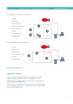
Страница 14: ...ose applicator connection 3 Use a screwdriver to loosen the two screws and separate the two parts of the protector and place it on the coupling Finally tighten the screws 4 Connect the electrical connections of the applicator male connector to the female connector of the hose 5 Place the applicator on its support Place the metal cable in the housing above the applicator grip Female thread Male thr...

Страница 15: ...is adapter the length of the coupling is longer than for the 8 mm hose therefore the thermal protector will not cover the entire hydraulic connection Double motor and air flow activation system Applicators with an electric trigger may have the option of activating both the motor and air flow This can be done by installing an auxiliary control box the connections to both the melter and the applicat...

Страница 16: ...LLATION 3 4 1 3 4 5 6 7 2 1 ON OFF switch 2 Air inlet to the electrovalve 3 Silencer 4 Air outlet from the electrovalve 5 Electrical connection to the applicator 6 Electrical connection to the melter 7 Electrical connection input ...

Страница 17: ...he applicator To use the applicator the corresponding melter will need to have pumping permission Make sure that the applicator is receiving air pressure 6 bar Pneumatic trigger Press the pneumatic trigger to allow air flow and open the module on the applicator to allow the adhesive to flow out of the nozzle To stop applying adhesive release the trigger to cut off the air supply to the module and ...

Страница 18: ...ressed A voltage signal is sent to the electrovalve to allow air supply to the module and start the application procedure The motor gear type melter in automatic mode activation contact closes so the melter pump operates only when the trigger is pressed 6 1 2 3 5 4 1 Air inlet 2 Pneumatic trigger 3 Mechanical choke 4 Module 5 Swirl mini module 6 Applicator body ...

Страница 19: ...r melter is supplied with a piston pump the flow is adjusted by the pressure regulator on the equipment If the Meler melter is supplied with a gear pump the flow can be adjusted two ways either by adjusting the motor revolutions preferably or by adjusting the pressure using the bypass valve 1 Air inlet 2 Electrovalve 3 Electric trigger 4 Electrical power supply 5 Mechanical choke 6 Module 7 Swirl ...

Страница 20: ...sure that the applicator is receiving a pressure of 6 bar The applicator is equipped with a mechanical air choke on the applicator body None of the side plates have to be removed to handle the air cut off all that is needed is a 4 mm Allen wrench to rotate the choke mechanism Turn the screw to the left to increase air flow and to the right to reduce it ...

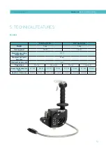
Страница 21: ...ower 175 W 260 W Maximum operating temperature 200ºC Maximum hydraulic pressure 80 bar Maximum air pressure 6 bar Trigger type Electric Pneumatic Electric Pneumatic Sensor and connector type Pt 100 Ni 120 Pt 100 Ni 120 Pt 100 Ni 120 Pt 100 Ni 120 Applicator reference 107100130 107100140 107100090 107100100 107200130 107200140 107200100 107200110 ...

Страница 22: ...tric trigger 8 Earth 1 Applicator heating resistance 2 Applicator heating resistance 3 Applicator temperature sensor 4 Applicator temperature sensor 5 Electric trigger 6 Electric trigger 8 Earth Version PT 100 Version Ni 120 with electric trigger Version Ni 120 1 Applicator heating resistance 2 Applicator heating resistance 3 Applicator temperature sensor 5 Applicator temperature sensor Earth Maxi...

Страница 23: ...erform the various tasks on the applicator as required for proper maintenance Access to the interior of the applicator MV applicators include three side plates to protect the user from possible burns To remove the side plates use an Allen wrench to remove the 3 screws that hold them together The side plates are easy to remove once the 3 screws have been loosened If the MV applicator has a 90º pneu...

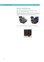
Страница 24: ...screws that connect the two body parts 2 Remove the housing gasket in the pneumatic distributor body and assem ble all the parts again Replacing the pneumatic trigger of the applicator 1 Remove the 2 screws that join the grip to the applicator body 2 Push the grip to separate it from the body This step should be performed carefully so the pneumatic tube gaskets are not lost during extraction Pneum...

Страница 25: ... and the screw that keeps the trigger connected to the grip All these steps can be performed using an Allen wrench 4 Pull the trigger up gently so that none of the pneumatic tube gaskets are lost 5 Replace the trigger and perform the steps in reverse order to assemble the applicator ...

Страница 26: ...plates do not have to be removed since these have holes prepared for the insertion of the Allen wrench 2 Slide the module downwards to remove it from the applicator B insert the new module and place the 2 screws Warning When removing the module make sure that the seating gaskets also come out and are not left inside Replacing the sensor and heating resistance Warning Before replacing the sensor or...

Страница 27: ...esistance heat the applicator a little to facilitate their extraction 4 Splice the wires of the new sensor or heating resistance with the wires from the applicator D To do this peel the ends of the wires twist them together and insert them in the ceramic cone E Once inserted rotate the cone clockwise until the wires are firmly in place in the cone F Note 2 cones will be necessary to replace a sens...

Страница 28: ...MELER GLUING SOLUTIONS 6 6 MAINTENANCE This page does not contain any text ...

Страница 29: ...e most common spare parts for manual MV applicators appears in this section providing a quick and reliable guide to choosing them Generic images of the spare parts are included as a visual aid and numbered to facilitate their identification in the list of spare part references and names ...

Страница 30: ...10110050 Straight pneumatic coupling 2 R0000096 O ring Ø5 x 1 5mm 3 150041760 Kit with 2 gaskets Ø6 07 x 1 78mm pneumatic trigger 4 150046230 Pt 100 sensor 4 150090300 Ni 120 sensor 5 07000007 JIC adapter coupling 9 16 to 3 4 6 106600040 NDS E Module 6 106200240 NDS Module A MANUAL APPLICATOR ASSEMBLY 4 3 2 1 5 6 ...

Страница 31: ...y 2 150115310 24V 1 1A Power supply 3 21110000 Complete electrovalve 3 2 5 4W 24 VDC 115001180 Double motor and air flow activation system No Ref Name 1 150100250 Hose support Ø8mm 2 150100260 Hose support Ø13mm 3 2 1 B DOUBLE MOTOR AND AIR FLOW ACTIVATION SYSTEM C HOSE SUPPORT OPTIONAL ...

Страница 32: ...MELER GLUING SOLUTIONS 7 4 SPARE PARTS LIST This page does not contain any text ...

Отзывы: