Kessy
Prog.
Operation
manual
‐
3
‐
3. Kessy Prog operation instruction
Turn on the programming tool by pressing ‘Return (Power)’ button for about 5 seconds. You can navigate
on-screen menu by mini-joystick, ‘Enter’ and ‘Return’ buttons. Pressing on the center of mini-joystick works
as ‘Enter’ button. Internal battery charge is indicated on a top right corner of the LCD-screen. If battery
charge is low connect provided 5V charging device to mini-USB port.
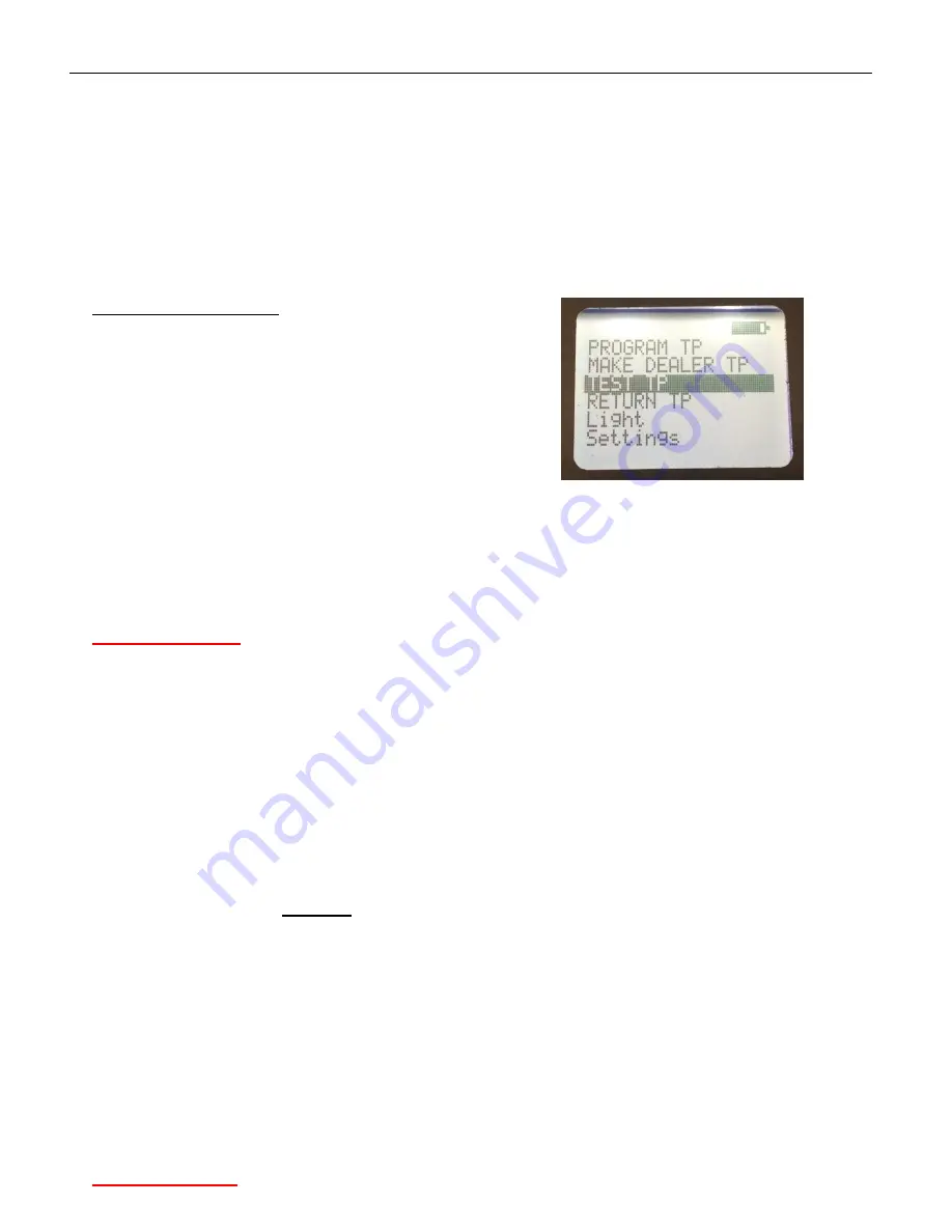
Onscreen menu sections:
•
‘Program TP’ – key or chip registration;
•
‘Make Dealer TP’ – dealer key preparation;
•
‘Test TP’– key or chip state check;
•
‘Return TP’– Kessy unit initial state recovery;
•
‘Light’ – built-in lighter on/off;
•
‘Settings’ – device parameters adjustment.
Pic.2 On screen menu.
3.1. Key programming function ‘Program TP’
This function includes key programming procedure and Kessy unit memory modification.
Please pay attention
:
keys or chips for registration must be unlocked. New keys or chips may be registered
once. After that they became locked. Looked keys cannot be registered in another Kessy unit.
Immobilizer systems with Kessy unit use only following types of transponders (HITAG2 group):
•
PCF7936 – single chip;
•
PCF7946 – transponder in original key without Keyless-Go;
•
PCF7943 – transponder in original key with Keyless-Go.
Electronic key with PCF7946 transponder and PCF7936 chip are fully functional right after registration
procedure. Registered original key with PCF7946 is able to start the engine and to lock/unlock doors.
PCF7936 chip is able to start the engine only.
Keyless-Go key (with
PCF7943
transponder) registration is performed in two steps:
•
Dealer key is prepared first with the help of ‘Make Dealer TP’ function (see chapter 3.2);
•
Prepared dealer key may be registered by means of dealer equipment (VAS or VCDS) using received in
step one PIN-code.
‘Program TP’ function involves following steps:
1)
Dismount Kessy unit, unplug connectors and take out internal board from its casing.
2)
Plug clip-connector cable into Kessy Prog device.
3)
Clean EEPROM chip pins on Kessy unit board.
4)
Plug clip-connector to EEPROM chip as shown on pic.3.
Please pay attention
:
red wire on clip-connector must be linked up with first pin on 93c86 chip.


