APPLICATION NOTE
RCD impedance uplift elimination.
Megger Ltd, Dover, United Kingdom
www.megger.com
Sales office: 01304 502 101,
RCD impedance uplift elimination
Technical support: 01304 502 120,
P2
The cause:
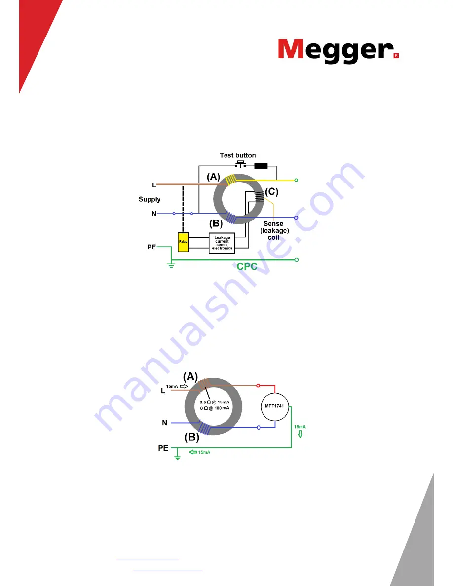
A typical circuit for an RCD is shown in Figure 1:
Figure 1. Typical RCD circuit.
Coils (A) and (B) are responsible for creating a current in the ferrite core of the RCD. When the current
in (A) and (B) differ, the sense coil (C) detects this current, if the difference is large enough the relay
disconnects the supply. It does not matter how much current is flowing in the L-N circuit, just the difference
is significant. Too much difference between (A) and (B) will trip the RCD.
The simplified circuit in Figure 2 shows just the 15 mA current induced by the MFT in the L-PE during a
non-trip test.
Figure 2. Simplified circuit
This 15 mA current is not enough to trip the RCD. This is a tiny test current, which is why the non-trip test
is so difficult for instrument manufacturers to produce successfully.


