Do not disconnect and connect the high voltage connectors many times to prevent
them from wearing and contamination. Silicone grease is already applied to both
connectors at the factory. It remains between the mating connectors for a very
long time and prevents discharge inside.
Step 4.
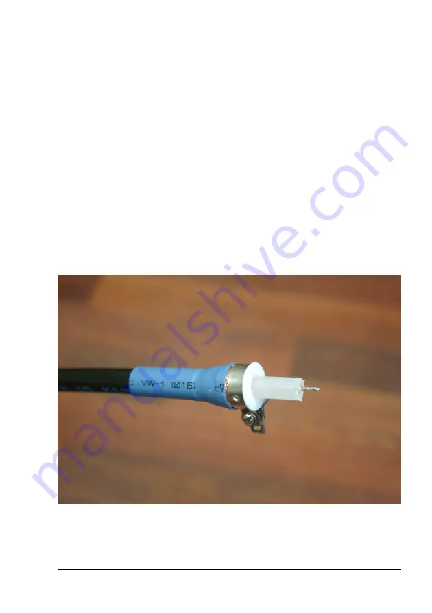
Connect another side of the coaxial cable to the load. The Teflon cone insulator is
installed on the cable end to prevent the barrier discharge between the central wire
and the cable braid across the cable solid polyethylene insulator (See Fig.2). You
may use additional wires for connection to the load. Solder the high voltage load
contact to the central cable wire and screw/solder ground load contact to the
ground cable clamp. Please keep the length of the wires between the coaxial cable
and the load as short as possible.
More than 10 cm additional wires between the load and the coaxial cable
result in excessive stray inductance and significantly decrease the pulse
amplitude on the load.
Fig.2. Teflon cone insulator on the cable end.
MEGAIMPULSE LTD. 10


