


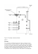


Refer to the installation schematic (fig 11, below) for details on the pipework
layout. Specific details for the discharge pipework layout is also provided in
figure 14.
●
All pipe fittings are made via BSP female pipe connections directly to the
unit.
●
A stopcock or servicing valve should be incorporated into the cold water
supply to enable
the cylinder and its associated controls to be isolated and serviced (not
supplied).
Figure 11: Typical installation schematic (not to scale)
page 15
Содержание Eco Plus Solar
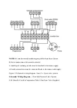
Страница 17: ...Figure 6 Three phase wiring schematic page 9 ...
Страница 51: ...page 29 Commissioning service records ...
Страница 52: ......
Страница 59: ...Megaflo Hurricane Way Norwich Norfolk NR6 6EA 36006204_issue_03 ...


