


EN
50
material being worked.
• Make sure that dust does not accumulate
at the workplace. Dust can easily ignite
and constitute a fire risk.
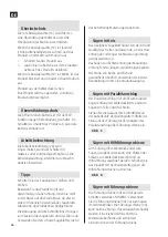
Fitting the dust extractor adapter
• Fasten the dust extractor adapter (29) on
the base plate (7) with the retaining screw
(28).
• A dust extractor hose with a diameter of
19 mm can be connected to the dust
extractor adapter (29).
• The dust extractor adapter must only be
fitted if an external dust extraction system
is connected. Otherwise the outfeed duct
can be damaged.
• Never fit a dust bag on the dust extractor
adapter, this can cause blockage in the
dust extraction system.
• Clean the dust extractor adapter (29) at
regular intervals for best functionality.
FIG. 3
External dust extraction
Connect the dust extraction hose (30) to a dust
extraction device (sold separately). Instructions
for connection of different dust extraction
devices are to be found at the end of the
instructions.
Only use dust extraction devices that are
suitable for the actual material.
A special dust extractor must be used if the
dust is dry and especially hazardous to health,
or carcinogenic.
HOW TO USE
Remove the battery before working on the
product.
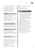
Adjusting the sawing depth
Adjust the sawing depth to the thickness of
the workpiece. Slightly less than one full tooth
on the blade should be visible below the
workpiece.
Undo the wing screw (17). Reduce the sawing
depth by pulling the product away from the
base plate (7), and increase the depth by
pressing the product against the base plate (7).
Set the required sawing depth according to the
scale (18) and tighten the wing screw (17).
Use thee reference marking (31) beside the
sawing depth scale (18) to adjust the sawing
depth.
FIG. 4
Adjusting the mitre/bevel angle
Place the product with the front of the blade
guard (13) on the surface.
Undo the wing screw (10). Swing the saw to
the side. Adjust to the required mitre angle
with the scale (9). Tighten the wing screw (10).
Use the reference marking (27) on the top
edge of the holder to adjust the mitre/bevel
angle.
NOTE:
During mitre sawing the sawing depth will
be less than the setting on the sawing depth
scale (18).
Mitre angle marking
The mitre angle marking 0° (12) shows the
position of the blade when sawing at right
angles. The mitre angle marking 45° (11)
shows the position of the blade when sawing
at an angle of 45°.
Starting
Inserting the battery
Содержание 019803
Страница 4: ...1 2 11 12 13 14 15 16 17 18 19 20 22 21 1 2 1 2 3 4 5 6 7 8 9 10 ...
Страница 5: ...3 4 5 23 24 25 26 14 13 27 28 60 mm ...
Страница 6: ...6 7 28 30 29 ...


