9
10
11
12
present readings as Relative reference value and display on secondary. Relative measurement has two
mode. one is REL
r
= measuring value - Reference value, the other is
REL%= (REL
r
/Reference value)
x 100% ( press SELECT to select REL
r
or REL% mode).
l
While SET button operating REL
r
button change as
u
(moving right) button.
l
Set up reference value for measurement .
1. In every function use RANGE select your range.
2. After press SET once, press SELECT twice the meter enter set up reference value for measurement.
At same time the
pqt
u
button are started.
3. Use
pqt
u
buttons set your reference value.
4. After set up, you can press SET to confirming.
l
Press REL
r
button more than 2 seconds the meter return to normal state.
8. SET
l
Press this button to starting
p
RANGE
q
2nd VIEW
t
MAX/MIN
u
REL
r
buttons. Use these
buttons set up your digits . At this condition the RANGE, 2nd VIEW, MAX/MIN, REL
r
original functions
are disabled.
l
Press this button more than 2 seconds backlight on and press this button again the backlight off.
The light can auto off after it on 30 seconds if does not press this button.
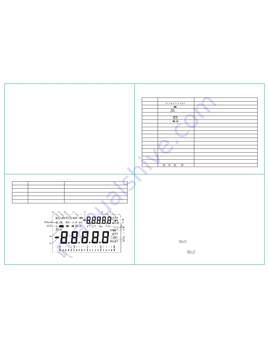
Display
Table 4. symbols of display
Order No.
Symbol
Description
1
Analog bar graph
2, 3,17
Negative sign
4
OUT
Square wave output
5
Hi
Hi frequency or themocoupIe indicate
6
Battery power is weakening
7
Diodelaudible continuity function
8
REL
r
%
Relative measurement
9, 19
DC, AC, DC+AC
DC,AC, DC+AC voltage or current
10
PH+ PH-
+ peak hold, - peak Hold
11
A-H
Auto Hold
12
AVG
Average reading
13
Auto
Auto mode
14
APO
Auto power off sign
15
RS 232
Communication on annunciation
16
MAX/MIN/MAX-MIN
MAX Reading, MlN Reading /MAX-MIN Reading
20
mV/V/mA/A
Second display volt and current unit
21
Hz/kHz/MHz/
V
/k
V
/M
V
Frequency and Resistance (ohms) unit [second]
22
%
%
ms
ms
Duty cycle unit, pulse width unit
23
nF/
m
F
Capcitance unit
24
mV/V/mA/A
Primary display volt and current unit
25
dBm
dBm annunciation
26
Hz/KHz/MHz/
V
/k
V
/M
V
Frequency and Resistance (ohms) unit (primary)
27,18
0
C
0
F
Temperature measurement indicate
28
RPM
Round/per minute
Figure 4. Display
Special functions
l
Auto power off
The meter has auto power off function, in normal conditions, when the meter is power on, if any push
buttons are not used or rotary switch is not changed, it can auto power off in 30 minutes after power on.
Before power off five minutes, the audible five beepers that points out the meter will power off. In operating
state any push button is used or rotary switch is changed the time of auto power off will recount.
l
Set up time for measurement
1. Press TIMER button to set time [ “0.00.00” appear at secondary display].
2. Press SELECT button the last digit of secondary display flash, at the same time, the
pqt
u
are
enable [The first digit of secondary display is hour, the second and third are minutes, tbe forth and fifth
are seconds].
1. Lise
pqt
u
buttons to select digit of time .
2. Press TIMER button again to confirming Complete this procedure measuring lime is starting .
l
Set limited measurement
The meter has set up limited or down limited measurement functions, up limited and down limited setting
as following.
1. Set Up limited : power on the meter
g
select range
g
press SET
g
press SELECT select Up limited
seting state (secondary display “
”) press moving buttons
pqt
u
to set digits
g
press SET to
confirm.
2. Set Down limited : power on the meter
g
select range
g
press SET
g
press SELECT select Down
limited seting state (secondary display “
”) press moving buttons
pqt
u
to set digits
g
press
SET to confirm.


