background image

10 

Fotos unverbindlich 

/ Non-contractual 

photographs

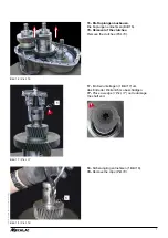
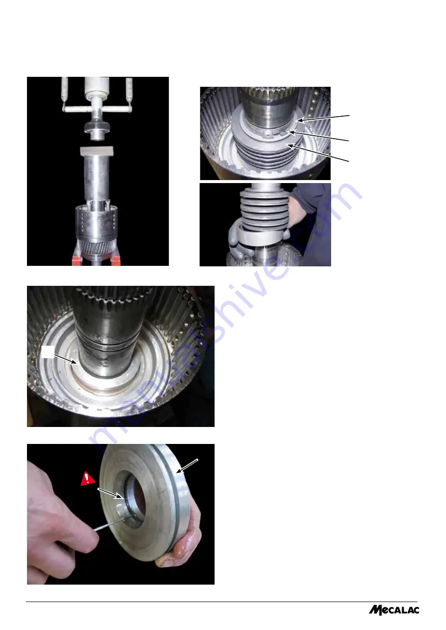
bild. 24 / 

Pict. 24

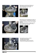
bild. 25 / 

Pict. 25

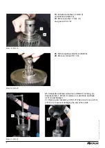
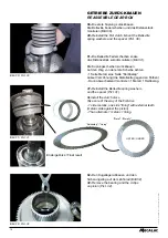
24- 

Mit Presse den Sicherungsring lösen der die 

Scheibe hält, und die belleville Federscheiben. 

24-


Use a press to loosen circlips which holds the


washer and remove the Bellleville spring washers.


25- 

ausbauen des kolbens (1 bild 25) mit Luftdruck 

im Druckeingang.

25- 

Removal of piston (1 Pict. 25) with air pressure 

in pressure orifice.

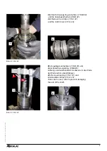
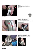
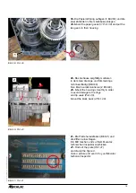
26-

 alle Dichtungen entnehmen ohne die alunute zu 

beschädigen (bild 26).

26-


Remove all the seals without damaging the alu 

groove (Pict. 26).

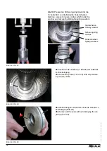
Sicherungsring

Circlips


Stützscheibe

Holding washer


Federscheiben

Spring washers 

1

bild. 26 / 

Pict. 26

Содержание 714MW

Страница 1: ...une fuite vous devez proc der son d pannage Proc dure Commander le Kit K565A8000 Voir plan de montage page suivante Proc dure r paration fuite sur bo te vitesse Betrifft 714MW bis Serien Nummer 80999...

Страница 2: ...u need to repair the gearbox Procedure Order Kit with partnumber K565A8000 See assembly instruction on the drawing attached Repair instructions for leakage on 714MW gearbox Con riferimento a 714MW fin...

Страница 3: ...e Cl s etc Echantillon de l OUTILLAGE n cessaire procedure r paration fuite sur boite vitesse 714MW Avant le d montage FR 1 2 Tous droits de reproduction r serv s pour tous pays Photos non contractuel...

Страница 4: ...e sup rieur Fig 1 2 Tirer l arbre c t moteur translation Fig 2 Fig 1 Arbre sup rieur Fig 2 3 Prendre la mesure au pied coulisse Fig 3 Fig 3 Arbre sup rieur 4 Pousser l arbre c t moteur translation Fig...

Страница 5: ...3 Photos non contractelles Prendre les pressions 6 D monter le bloc et joint plat Fig 4 et 5 en s assurant de la pr sence des joints toriques Fig 6 Fig 4 Bloc Fig 5 Fig 6...

Страница 6: ...7 8 Mettre en pression 1 5 bar maximum les deux arbres 1 et 2 Fig 8 V rifier qu au bout d environ 3 min la pression soit toujours identique 9 V rifier la pression de frein de parc Doit tre 8 bars Cons...

Страница 7: ...g 10 Fig 11 Fig 12 d montage de la bo te 10 Extraire le piston de frein Fig 10 11 Extraire la bague d tanch it interm diaire Fig 11 12 D poser les disques 1 Fig 12 et contr ler l tat de surface des po...

Страница 8: ...en place un anneau de levage 1 Fig 13 14 D poser la visserie du carter Fig 14 et tourner caler la bo te vitesse cale d environ 13 cm 15 Lever avec pr caution le carter afin de ne pas endommager les se...

Страница 9: ...non contractelles 16 D montage des embrayages D poser les embrayages Fig 16 17 Placer une cale 1 Fig 17 pour ne pas endommager le bout de l arbre 18 D poser le clips 1 Fig 18 1 1 Fig 16 Fig 17 Fig 18...

Страница 10: ...es Fig 19 19 D poser la cale 1 Fig 19 et le pignon 2 Fig 19 20 D poser le clips Fig 20 21 D poser le pignon complet 2 Fig 21 Attention placer une cale 1 Fig 21 pour ne pas endommager le bout de l arbr...

Страница 11: ...s Fig 22 Fig 23 22 D poser le clips 1 Fig 22 et les disques d embrayage 2 Fig 22 2 1 1 2 23 D poser le roulement 1 Fig 23 et le clips interm diaire 2 Fig 23 Attention placer une cale pour ne pas endom...

Страница 12: ...r sortir le clips retenant cale et rondelles Belleville 25 Extraction du piston 1 Fig 25 l aide d une soufflette par l orifice de pression 26 D poser tous les joints en prenant soin de ne pas endommag...

Страница 13: ...les joints toriques en prenant soin de ne pas les vriller Fig 27 28 Remonter les joints composites apr s les avoir fait ramollir dans de l eau chaude Fig 28 Attention au sens S aider d un outil lisse...

Страница 14: ...u 1er disque 1 face m tallique 1 face garniture denture externe c t m tallique contre le piston puis intercaler 1 m tallique 1 garniture R sultat final REMONTAGE de la boite DESSOUS garniture m talliq...

Страница 15: ...lips sur l arbre 2 Fig 33 34 Embo tement du 1er roulement sans tanch it et des clips 1 Fig 34 Embo tement du 2 me roulement avec tanch it l ext rieur et des clips 2 Fig 34 Fig 33 2 1 Fig 34 2 1 Fig 35...

Страница 16: ...saire changer les segments Fig 36 1 Fig 37 Fig 38 38 Proc der de la m me fa on pour remonter le second embrayage Fig 38 Voir page 12 0 1 mm 2 37 Prendre les cales n cessaires en fonction de la mesure...

Страница 17: ...r les 2 pignons dans leur carter 41 Rep rer la plaque Fig 41 et frapper le chiffre 4 Prendre une photo et envoyer la votre inspecteur technique Mecalac Fig 41 1 40 Reposer le carter avec pr caution af...

Страница 18: ...ckage von 714MW Repair instructions for leakage on 714MW gearbox 714MW Vor dem Zerlegen Before disassembling DE GB 1 2 Die Vervielf ltigung dieser Publikation ist auch in Ausz gen untersagt und gilt a...

Страница 19: ...n shaft on hydraulik motor side Pict 2 Bild 1 Obere Welle Pict 1 Upper shaft Bild 2 Pict 2 3 Mit Schublehre messen Bild 3 3 Measure with caliper Pict 3 Bild 3 Obere Welle Pict 3 Upper shaft 4 Auf die...

Страница 20: ...KE ABLESEN MEASURE THE PRESSURES 6 Den Block und die Flachdichtung abbauen dabei sichern dass die O Ringe anwesend sind Bild 6 6 Remove the block and the flat seal securing the presence of the Orings...

Страница 21: ...dass nach 3 Minuten der Druck gleich geblieben ist 8 Put both shafts under pressure maximu 1 5 bar 1 and 2 Pict 8 Check that the pressure holds at least 3 minutes 9 Den Feststellbremsedruck pr fen Mus...

Страница 22: ...THE GEARBOX 10 Bremskolben heraus ziehen Bild 10 10 Extract the brake piston Pict 10 11 Zwischendichtungsbuchse heraus ziehen Bild 11 11 Extract the inbetween seal bushing Pict 11 12 Die Scheiben ent...

Страница 23: ...d turn the gear box and wedge up 14 Die Schrauben von dem Geh use entnehmen Bild 14 14 Remove the screws of the housing Pict 14 Keil circa 13 mm Wedge about 13 mm 15 Das Geh use sorgf ltig heben um di...

Страница 24: ...16 16 Removal of the clutches Remove the clutches Pict 16 17 Ein Keil unterlegen 1 Bild 17 um das Ende der Welle nicht zu besch digen 17 Place a wedge 1 Pict 17 not to damage the shaft end 18 Sicherun...

Страница 25: ...2 Pict 19 20 Sicherungsring entnehmen Bild 20 20 Remove circlips Pict 20 21 Komplettes Zahnrad entnehmen 2 Bild 21 Achtung ein Zwischenst ck 1 Bild 21 montieren um das Ende der Welle nicht zu besch d...

Страница 26: ...22 22 Remove the circlips 1 Pict 22 and the clutch discs 2 Pict 22 2 1 1 2 23 Kugellager entnehmen 1 Bild 23 und Zwischensicherungssring 2 Bild 23 Achtung ein Zwischenst ck montieren um das Ende der...

Страница 27: ...s the washer and remove the Bellleville spring washers 25 Ausbauen des Kolbens 1 Bild 25 mit Luftdruck im Druckeingang 25 Removal of piston 1 Pict 25 with air pressure in pressure orifice 26 Alle Dich...

Страница 28: ...ict 27 28 Die Kompositdichtungen montieren nachdem man die im warmen Wasser aufgeweichert hat Bild 28 Auf den Weg aufpassen Sich helfen mit einem glatten Werkzeug 28 Mount the composite seals after ha...

Страница 29: ...t 31 Reinstall the clutch discs Take care of the way of the first disc 1 side metalic one side lining with external teeth metalic side against the piston Than alternate 1 metalic 1 lining Endergebniss...

Страница 30: ...montieren 1 Bild 35 die Distanzsscheibe 2 Bild 35 und Sicherungsring 3 Bild 35 35 Mount the gear 1 picture 35 the spacer 2 picture 35 and retaining ring 3 picture 35 3 2 1 34 Montage des ersten Kugel...

Страница 31: ...Pict 38 38 Gleiches Verfahren um die zweite Kuplung zu montieren Bild 38 Siehe Seite 12 38 Proceed the same to mount the second clutch Pict 38 See page 12 0 1 mm 2 37 Die ben tigte Unterlegscheiben n...

Страница 32: ...die Ziffer 4 einschlagen Ein Bild machen und zu Ihrem Mecalac technischen Inspektor zuschicken 41 Find out the plate Pict 41 and stamp the figure 4 Take a picture and send it to your Mecalac technical...

Отзывы: