


WLS-TC User's Guide
Functional Details
17
Status LEDs
The LEDs indicate the communication status of USB and wireless operations. In addition, three LEDs indicate
the signal strength of data transmitted over the wireless link. Refer to the table below for the function of each
LED.
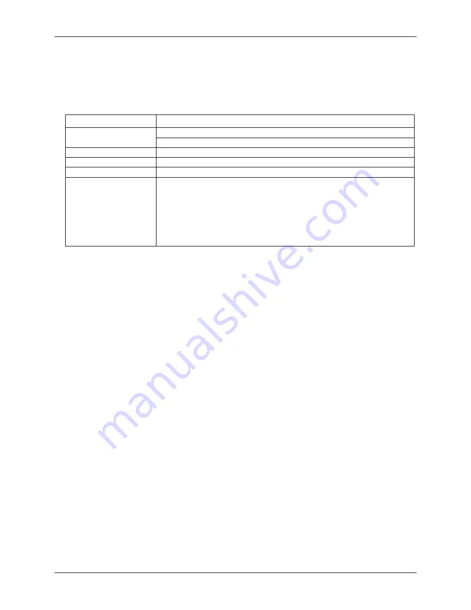
LED functions
LED
Function
Command
Steady green – the WLS-TC is connected to a computer or AC adapter
Blinking green – the WLS-TC is receiving a command over the USB or wireless link.
Wireless Power (green)
The WLS-TC device's internal RF module is receiving power (USB or AC adapter)
Transmit (yellow)
Data is being transmitted over an active wireless link.
Receive (red)
Data is being received over an active wireless link.
Received Signal Strength
(RSS) indicators LEDs
3 green LED bar graph. The LEDs will turn on when receiving a wireless message and
stay on for approximately 1 second after the end of the message. They indicate the
amount of fade margin present in an active wireless link. Fade margin is defined as the
difference between the incoming signal strength and the device’s receiver sensitivity.
Three LEDs on: Very strong signal (> 30 dB fade margin)
Two LEDs on: Strong signal (> 20 dB fade margin)
One LED on: Moderate signal (> 10 dB fade margin)
No LEDs on: Weak signal (< 10 dB fade margin)
LED Test button
The LED test button tests the functionality of the LEDs. When pressed, each LED lights in sequence (first the
Command LED then left to right from the Wireless Power LED to the RSS indicator LEDs).
USB connector
The USB connector pr5V power and communication. External power is required to operate the WLS-
TC remotely through the wireless interface.
For local operation, connect to the USB port or hub on your computer. For remote wireless operation, connect
to the AC-to-USB power adapter that shipped with the device.


