background image

CHECK

ING

VALVE CHECKING AND SETTING

The SEASONTROL head pressure control valves are
factory set and checked to maintain a minimum head
pressure equivalent to 90F condensing. The valves
have a nominal 15 psig modulating range between fully
open and fully closed positions. Typical settings for

R-22 use is to have the valves modulate between 160
and 175 psig. This will maintain a nominal 90F con-

densing.

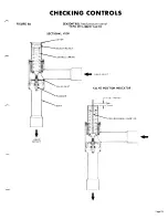
Referring to the sectional diagrams, it is to be 

noted

that on pressure  increase on the system, the pressure
will tend to compress the bellows and the valve stroke
will be up or toward the adjustment end of the valve.

This also applies to the 237 series valves. The 239
series, or liquid valves, open on pressure rise. The

valve travel is a nominal one tenth inch for all models.

As indicated in the diagrams, the adjustment of the

nut in a clockwise direction will increase the modu-
lating pressure point. A wide bladed screwdriver or

similar tool inserted into the nut slot may be used for
making the adjustment. Turning the adjustment nut

clockwise raises the control point.

The modulating pressure point and range may be

checked as follows:

A. Make up a “depth gauge” for inserting through the

adjusting nut opening and long enough to hit the

CONTROLS

B.

C.

D.

E.

bottom of the bellows section as indicated in the
diagrams. A piece of insulated wire, 8 to 12

gauge, is a simple and convenient method to make
a gauge. Insert a piece of the wire into the valve
as shown in diagrams. Trim off insulation, for

about one inch of the end to be inserted, and at a
point just above the top of the valve at the other

end. Hold the gauge down lightly against the bel-

lows and sight along the top of valve.

A high side gauge should be connected to a line

so it can be brought to the valve area while valve

observations are being made.

Start up the unit and note pressures at which valve
bellows rise. We assume that the pressure was low
enough at start up so that the bellows is in the
down position. The test may also be done in re-
verse by running the system upto a high head pres-
sure, stopping the unit, and making observations
at what pressure the valve changes position.

The valves should he set so that tho movement of
both valves is through the same pressure range.

Be sure system has sufficient refrigerant before

assuming valves are out of adjustment.

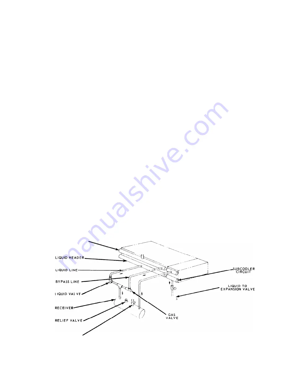
FIGURE 8A

SEASONTROL III 

head pressure control

For operation at OF ambient.

H O T   G A 5   H E A D E R

P U R G E   V A L V E  

Page  22

Содержание Seasonpak PAB Series

Страница 1: ...15 AUGUST 1967 FORM 206034Y INSTALLATION AND MAINTENANCE DATA MODEL PAB AIR COOLED WATER CHILLER 7 1 2 THRU 60 TONS INC 13600 INDUSTRIAL PARK BLVD P O BOX 1551 MINNEAPOLIS MINNESOTA 55440 PHONE 377 97...

Страница 2: ......

Страница 3: ...Lability not strictly in accordan further warranty is h this policy except to the extent that such in writing and signed by an official of Mc Quay for additional consideration n in accordance with an...

Страница 4: ...charge for the job requirements see Table 6 Pages 8 and 9 Charge for specific units can be obtained f rom the nameplatc The McQUAY line of air cooled water chillers is de signed for outdoor applicatio...

Страница 5: ......

Страница 6: ......

Страница 7: ......

Страница 8: ......

Страница 9: ......

Страница 10: ......

Страница 11: ...s covering specific rcquircments CRANKCASE HEATERS The compressors are equipped with crankcase heaters Some models have heaters installed externally below the crankcase and others have heaters inserte...

Страница 12: ......

Страница 13: ......

Страница 14: ......

Страница 15: ......

Страница 16: ......

Страница 17: ...Check to see that the water temperature thermo stat is installed in the entering water line The L thermostat well is to be full of heat conducting compound and the bulb must be secured with the retain...

Страница 18: ...graph E B Turn pumpdown switches S3 and S4 to auto posi tion Check liquid sight glass ahead of expansion valve for proper refrigerant charge C Observe operation for several minutes noting un usual sou...

Страница 19: ...or at the unit an impedance relay is incorporated in the control circuit Basically this type of control is centered around a relay with a high impedance holding coil connected in series with the basic...

Страница 20: ...low side of the system and its purpose is to shut down the D E compressor at the end of the pumpdown cycle It will open at 35 psig and automatically reset at approximately 60 psig The control can be c...

Страница 21: ...een switches Do NOT make any adjustments other than the dial as this is a preset precision control TO CHANGE THE SET POINT 1 2 3 Loosen the setscrews on the collar below the hex nut see Fig 7 Turn the...

Страница 22: ...checked as follows A Make up a depth gauge for inserting through the adjusting nut opening and long enough to hit the CONTROLS B C D E bottom of the bellows section as indicated in the diagrams A piec...

Страница 23: ......

Страница 24: ...t the nuisance of water dripping from the lines If insulation is not of the self contained vapor barrier type it should be covered with a moisture seal Do not insulate piping until it has been tested...

Страница 25: ...on chamber on the motor end of the compressor Shut off valves E F G VIEW FROM END OF COOLER STRAIGHT PIPE EE D x D x 1 are never installed in these control lines The compressor is pre charged with suf...

Страница 26: ...or of the moisture indicator button is an indication of the dryness of the system and is ex tremely important when the system has been ser v i c e d Immediately after the system h a s been opened for...

Страница 27: ...nto heavy duty steel tube sheets and s c a l e d by a cast steel refrigerant head B The water connection nozzles which enter and leave the shell are on the same side of the unit No special attention i...

Страница 28: ...e s s d D i s c h a r g e s h u t o f f v a l v e p a r t i a l l y d O p e n v a l v e c l o s e d L o w D i s c h a r g e P r e s s u r e a F a u l t y c o n d e n s e r t e m p e r a t u r e r e g...

Страница 29: ...A d j u s t t h e r m a l e x p a n s i o n v a l v e C o m p r e s s o r l o s e s o i l a L o c k o f r e f r i g e r a n t b E x c e s s i v e c o m p r e s s i o n r i n g b l o w b y a C h e c k...

Страница 30: ...ng parts refer to the model number and serial number of with an explanation of the malfunctions and a descrip the unit as stamped on the serial plate attached to the tion of the replacement parts requ...

Отзывы: