D3
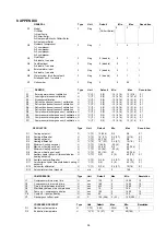
Maximum duration of defrost cycle
U
min
10
1
40
1
D4
Defrost interval time
U
min
45
0
199
1
D5
Delay before defrosting
U
sec
0
0
1990
10
D6
Delay after defrosting
U
sec
120
0
1990
10
COOL MODE ANTIFREEZE
Type
Unit
Default
Min
Max
Resolution
A1
Antifreeze heater set-point
U
°C ( F)
5 (41)
-40 (-40)
40 (104) 1
A2
Antifreeze heater differential
U
°C (°F)
2 (3.6)
0.4 (0.7)
10 (18)
0.1
A3
Antifreeze sensor select
0=Leaving water, 1=Entering water
U
Flag
0
(leaving)
0
1
1
A4
Antifreeze alarm set-point
U
°C (°F)
3 (37)
-40 (-40)
40 (104)
1
A5
Antifreeze alarm differential
U
°C (°F)
2 (3.6)
0.4 (0.7)
10 (18)
0.1
ALARM AND CONTACT
Type
Unit
Default
Min
Max
Resolution
P1
Flow switch confirmation time
U
sec
5
0
199
1
P2
Flow switch alarm delay at pump start
U
sec
120
0
199
1
P3
Low pressure alarm delay at compressor start-up U
sec
30
0
199
1
P4
Comp overload alarm reset type
U
Flag
0
0
1
1
0=Manual reset, 1=Auto reset
(manual)
P5
High pressure alarm reset type
U
Flag
1
0
1
1
0=Manual reset, 1=Auto reset
(auto)
P6
Low pressure alarm reset type
U
Flag
1
0
1
1
0=Manual reset, 1=Auto reset
(auto)
P7
Fan overload alarm reset type
U
Flag
1
0
1
1
0=Manual reset, 1=Auto reset
(auto)
P8
Pump overload alarm reset type
U
Flag
0
0
1
1
0=Manual reset, 1=Auto reset
(manual)
P9
Flow switch alarm reset type
U
Flag
0
0
1
1
0=Manual reset, 1=Auto reset
(manual)
P10
Auxiliary alarm reset type
U
Flag
1
0
1
1
0=Manual reset, 1=Auto reset
(auto)
P11
Antifreeze alarm reset type
U
Flag
1
0
1
1
0=Manual reset, 1=Auto reset
(auto)
P12
Comp overload contact type
U
Flag
0
0
1
1
0=Normally close (NC)
1=Normally open (NO)
(NC)
P13
High pressure contact type
U
Flag
0
0
1
1
0=Normally close (NC)
1=Normally open (NO)
(NC)
P14
Low pressure contact type
U
Flag
0
0
1
1
0=Normally close (NC)
1=Normally open (NO)
(NC)
P15
Fan overload contact type
U
Flag
0
0
1
1
0=Normally close (NC)
1=Normally open (NO)
(NC)
P16
Pump overload contact type
U
Flag
0
0
1
1
0=Normally close (NC)
1=Normally open (NO)
(NC)
P17
Flow switch contact type
U
Flag
0
0
1
1
0=Normally close (NC)
1=Normally open (NO)
(NC)
P18
External alarm contact type
U
Flag
0
0
1
1
0=Normally close (NC)
1=Normally open (NO)
(NC)
P19
Defrost end contact type
U
Flag
0
0
1
1
0=Normally close (NC)
1=Normally open (NO)
(NC)
35
Содержание M4AC 080 C
Страница 10: ...5 2 Menu Structure Menu Structure Diagram for Chiller 9...
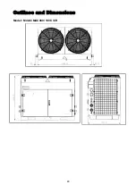
Страница 49: ...Outlines and Dimensions Model M4AC MAC080 100 C CR 48...
Страница 50: ...Model M4AC MAC120 150 C CR 49...
Страница 52: ...Wiring Diagrams Model M4AC MAC080 100 120 150C Isolator Switch 51...
Страница 53: ...Model M4AC MAC080 100 120 150C Terminal Block 52...
Страница 54: ...Model M4AC MAC080 100 120 150CR Isolator Switch 53...
Страница 55: ...Model M4AC MAC080 100 120 150CR Terminal Block 54...
Страница 68: ...2004 McQuay International 1 800 432 1342 www mcquay com ISO 9002 REGISTERED...


