10
OM
AGSB-5
Control Operation
This section on MicroTech II control is divided into four subsections:
•
Circuit Controller, explains the functions of the circuit controller, see page 10.
•
Unit Controller, explains the functions of the unit controller, see page 24.
•
Using the Controller, explains how to navigate through the menus and how to make
entries, see page 37.
•
Screen Content, details the menu screen content and how to use them, see page 41.
Circuit Controller
Inputs/Outputs
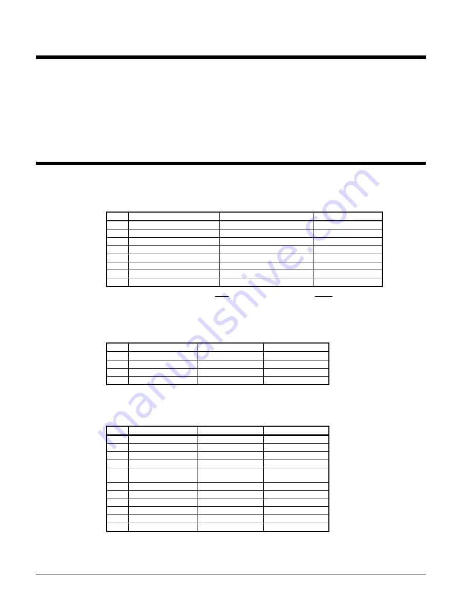
Table 1, Analog Inputs
# Description
Signal
Source
Range
1
Evaporator Pressure
0.5 - 4.5 VDC (NOTE)
0 to 132 psi
2
Condenser Pressure
0.5 - 4.5 VDC (NOTE)
3.6 to 410 psi
3
Liquid Pressure
0.5 - 4.5 VDC (NOTE)
3.6 to 410 psi
4
Suction Temperature
Thermistor (10k@25°C)
-58
°
F to 212°F
5 Discharge
Temperature
Thermistor
(10k@25°C)
-58
°
to 212°F
6
Liquid Temperature
Thermistor (10k@25°C)
-58 to 212°F
7
Slide Load Indicator
4 to 20 mA
0 to 100%
8 Open
NOTE
: Value at the converter board input. Value at the converter board output is 0.1 VDC – 0.9 VDC.
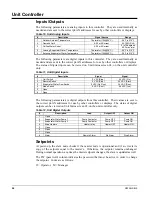
These parameters are analog inputs to the circuit controller. They are used internally as
needed and are sent to the correct pLAN addresses for use by other controllers or displays.
Table 2, Analog Outputs
# Description Output
Signal
Range
1
Fan 1&2 VFD
0 to 10 VDC
20 to 60 Hz
2 Open
3
EXV Driver
0 to 10 VDC
0 to 6386 steps
4 Open
These parameters are analog outputs from this controller. The values are sent to the correct
pLAN addresses for use by other controllers or displays.
Table 3, Digital Inputs
# Description
Signal
Signal
1
Circuit Switch
0 VAC (Off)
24 VAC (Auto)
2 Open
3
Starter Fault
0 VAC (Fault)
24 VAC (No Fault)
4
VFD Fault
0 VAC (Fault)
24 VAC (No Fault)
5
Oil Differential
Pressure Switch
0 VAC (Fault)
24 VAC (No Fault)
6
Mech High Pressure
0 VAC (Fault)
24 VAC (No Fault)
7
Low Pressure Switch
0 VAC (Fault)
24 VAC (No Fault)
8 Open
9
Oil Level Sensor
0 VAC (Fault)
24 VAC (No Fault)
10 Open
11 Open
Содержание AGS 206A
Страница 65: ......


