background image

iScout® System User’s Manual


32 

© McQ Inc 2008 

5.2.4


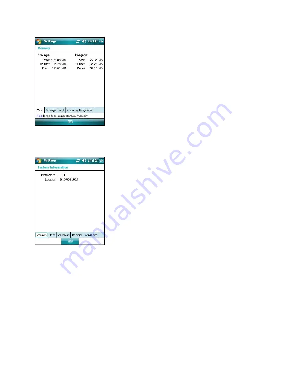
Memory 

Tap 

System | Memory

 to display the 

Settings Memory 

screen 

(Figure 5-9), to see how much Storage memory (Flash) 

and Program memory. 


5.2.5


System Information 

Tap 

System | System Information 

to display the 

Settings | 

System Information screen

 (Figure 5-10).  Information that 

can be found here includes firmware version, serial number, 
processor speed, RAM and Flash size, plus battery and card 
port information. 


Figure 5-9:  Settings | Memory 

Screen 


Figure 5-10:  Settings | System 

Information Screen 

Содержание iScout System

Страница 1: ...em User s Manual April 2 2008 Version 1 2 McQ Inc 1551 Forbes Street Fredericksburg VA 22405 540 373 2374 info mcqinc com OmniSense and iScout are the Registered Trademarks of McQ Inc Copyright McQ Inc April 2008 ...

Страница 2: ......

Страница 3: ...atteries into Battery Housing 10 Connecting the Battery Box to the LHCN Housing 11 Changing the Batteries in the LHCN Housing 12 2 2 2 Configuring the LHCN 12 Establishing Communications with the LHCN 13 Configuring the LHCN 14 3 ISCOUT SENSOR SET UP 17 3 1 Set Up Procedure for iScout Sensor 18 3 2 iScout Normal Mode 21 3 3 Sleep Mode 21 3 4 Tamper 22 4 ISCOUT DEPLOYMENT GUIDANCE 23 4 1 Using the ...

Страница 4: ...end 37 5 4 2 Window Menu Preferences 37 Preferences Comm Ports 38 Preferences HHPM Settings 38 5 4 3 Window Menu Detections 41 5 4 4 Window Menu Device List 42 5 4 5 Window Menu Images 42 5 4 6 Window Menu Switch Sensor 42 5 4 7 Window Menu GPS On 42 5 4 8 Window Menu Exit 42 5 5 Devices Menu 43 5 5 1 Devices Menu Discover Devices 43 5 5 2 Devices Menu Request Status 43 Device Name 43 Status Time ...

Страница 5: ... Menu Set Operational 49 5 5 8 Devices Menu Switch CDIF 50 6 TECHNICAL SUPPORT 51 6 1 Maintenance 51 6 2 Training 51 6 3 Installation 51 6 4 Configuration Management and Program Support 51 6 5 Contact Information 51 7 END USERS LICENSE AGREEMENT 53 8 APPENDIX A FCC UNITED STATES CERTIFICATION 58 ...

Страница 6: ...M Algorithms Tab 22 Figure 4 1 iScout Sensor and Switch Cable 24 Figure 4 2 Switch closure Specifications and Usage Guidelines 25 Figure 5 1 Power Menu 27 Figure 5 2 Keyboard Icon 28 Figure 5 3 Windows Alphabetic and Numeric Keyboards 28 Figure 5 4 Battery Status and Notification LEDs 29 Figure 5 5 Nomad Settings Screen 30 Figure 5 6 Settings Backlight 30 Figure 5 7 Settings Time Screen 31 Figure ...

Страница 7: ...nel 46 Figure 5 29 Mark Button No GPS Fix 46 Figure 5 30 HHPM Location Panel with GPS Off 47 Figure 5 31 HHPM Comms Panel 47 Figure 5 32 HHPM Transducers Panel 48 Figure 5 33 HHPM Algorithms Panel 48 Figure 5 34 HHPM Sleep Panel 49 Figure 5 35 Begin Operation Confirmation 49 Figure 5 36 Switch CDIF Message 50 ...

Страница 8: ......

Страница 9: ...e remotely monitored via the Iridium satellite system Each kit has up to six iScout sensors one HHPM one WMR one LHCN one battery housing for three BA series batteries two sets of lithium AA batteries for the iScout sensors one charger for the HHPM and the WMR an external battery pack connector microphone port water sealing plug PIR lens protective caps for each iScout antennas for each iScout for...

Страница 10: ...ink between the WMR and HHPM through the OmniSense program Once the link between the WMR and the HHPM has been established the data will appear on the HHPM from the iScout with no interference Also available is communication with the iScout sensor via either the OmniSense ISU or via a LHCN relay 1 1 iScout Sensor Description The iScout sensor node s purpose is to detect activity in a specific area...

Страница 11: ...can communicate with OmniSense sensors through the 900 MHz link to command images and send detections over Iridium if necessary A Long Haul Comms Node LHCN can send iScout messages and forward backend command and control messages via the Iridium satcom link 1 1 1 iScout Features Size 3 x 3 x 1 Inches Weight 8 Oz Op Temperature Range 20 C to 60 C Power Two internal AA Batteries Lithium preferred or...

Страница 12: ...se Ø Commands OmniSense Pictures Ø Communicates Through OmniSense Positive Indication of Unit Comms Link Status Accurate Timestamp of Activities From GPS and Internal Clock Emplacement Mode for Easy Installation and Set Up Normal Mode Provides Automated Operation Sleep Mode Programmable by Operator Tamper Report with Option to Disable Sensor or Continue Tamper Reports Unique ID for Each Sensor Plu...

Страница 13: ...switch located on the top of the box When the switch is turned to the On position the Power LED turns green If the WMR is in the Off position the Power LED is not on The second LED or Battery LED on the WMR shows when the unit is being charged The unit is red when it is charging and green when the charge has exceeded 90 of battery capacity The connector for the battery charger is located on the si...

Страница 14: ...ring the unit with an external 12 VDC power source or use with a serial cable which allows the HHPM to communicate directly with the unit Built In Functionality 1 Satellite Communications o Relay traffic between the sensor fields and OmniSense Backend 2 Terrestrial RF Communications o Provides a Communications Hub for Sensor Fields Self locating via an internal GPS module o Antenna TNC connector f...

Страница 15: ...or the user These displays show the detections in time order show the sensor detections on a map as shown in Figure 1 5 right and display status reports received from the sensor Additionally the individual sensors have the capability to send their location and configuration via relays to the SADU at a central monitoring location 1 4 1 HHPM Features Battery Powered Lithium Ion Rechargeable Rugged S...

Страница 16: ...roper installation of the antenna on LHCNs and the associated OmniSense sensing units Cores or iScouts Sensing units should be placed no more than 1 kilometer from a LHCN line of sight If the Sensor antenna is located on or near the ground mounting the LHCN antenna on a tower or high ground will extend the RF range The terrestrial local communications system can also operate on one of ten channels...

Страница 17: ... deployment of the LHCN and then allow more fully trained personnel to use the OmniSense system s remote configuration capability to tailor the LHCN once it is in place 2 2 1 LHCN Installation Installing the Local Comms Antenna to the LHCN Housing NOTE Refer to Figure 2 1 throughout this procedure 1 Secure the Local Communications antenna either on the antenna connector on the LHCN case or remote ...

Страница 18: ...ure 2 2 throughout this procedure 1 Remove the battery from its package and ensure the protective cap is removed from the battery connector 2 Open the metal battery housing completely Ensure that the hinged part is completely open or the batteries will not slide into the connectors 3 With the base of the battery slightly angled upward align the battery connector with the connector on the Battery H...

Страница 19: ...y Box to the LHCN housing until all antennas have been connected Connecting the Battery Box to the LHCN Housing 1 Connect the battery box to the LHCN housing a Place the base of the battery box on the ground so that the LHCN housing is skyward b Line up the black power connector on the battery housing with the mate on the LHCN housing c Push two units together so that both are mated d Fasten the f...

Страница 20: ... Using the HHPM WMR and using the RF communications link between the HHPM and the unit An RF connection must be established between the HHPM WMR and the Unit prior to being able to configure the unit 3 Using satellite communications and the backend OmniSense applications software SADU This method is usually not used during the initial installation and is used only after the unit has been configure...

Страница 21: ...t and the WMR 2 Using the HHPM OmniSense application software under the Windows tab select Preferences Comm Ports 3 In the Comm Ports menu select Bluetooth WMR then select OK 4 Under the Windows tab select Switch Device This will bring up a window with all the devices that the HHPM is currently linked to via Bluetooth Select the Find button and the HHPM will refresh this list 5 Once the Find funct...

Страница 22: ...it has passed the BITE Go to the Devices Menu Figure 2 4 left and choose the Request Status option The screen will only display the results of the BIT failures Figure 2 4 right Ensure that there are no BIT failures 4 Confirm that the LHCN has successfully sent at least one SBD message by checking the SBD row of the SATCOM Succ Att section If this reads 0 0 successful the sensor will continue to re...

Страница 23: ...he Status Report Interval using the slider and enter in the Network ID that the unit is to operate on c Algorithms tab Select the action desired if a tamper occurs Figure 2 5 i Off Tamper detection disabled ii Report Tamper Only Tamper detection sent unit continues to operate normally iii Report and Disable Tamper detection sent and unit becomes disabled unit can be recovered by plugging into the ...

Страница 24: ...erified select OK in the upper right hand corner then No when asked Configure Device 10 Using the HHPM select the Begin Operation from the Devices Menu 11 A recommended procedure is to request a status from the unit after it has begun normal operations Once the status has been received the LQI button will display a table indicating RF signal strength of nearby units 12 Disconnect the HHPM cable fr...

Страница 25: ...are two basic modes of operation for the sensor unit Emplacement Mode used to configure the sensor and Normal Mode the mode for standard monitoring operations A third mode called Sleep is a programmable mode that disables the sensor s detection abilities to save power but is only used if programmed by the user Figure 3 1 Hand Held Programmer Monitor HHPM and Wireless Remote Relay WMR ...

Страница 26: ...s and therefore only applications specific to the set up of the iScout sensor will be addressed here 1 Turn on the WMR by turning the black knob on the top of the device Figure 3 1 2 Turn on the HHPM and start the OmniSense application Make sure that the HHPM Communication Preference Figure 3 2 is set to Bluetooth WMR See Comms Preferences in Section 5 4 2 Figure 3 2 Comms Port Window ...

Страница 27: ...y turning it counter clockwise Insert two new lithium AA batteries note polarity markings CAUTION Use two new batteries DO NOT put in two used batteries or a combination of new and used batteries 5 Put the Battery Switch Cover back over the battery compartment making sure to line up the locking tabs Rotate the cover clockwise to secure it as shown in Figure 3 4 left 6 Attach the antenna to the top...

Страница 28: ...nsure Bluetooth WMR is selected and that a Bluetooth connection has been verified with a popup message on the HHPM Also check to make sure that the WMR is completely charged b Flashing GREEN with a pattern of flashing 20 times at once each second it lights GREEN every second for twenty seconds and then goes out indicates a successful transmission and receipt of the power on Configuration message 9...

Страница 29: ...ion 2 the sensor must send in a report to the HHPM to initiate communications and to allow a return message configuration request or command be sent back to the sensor unit 3 Adjust the configurable settings as desired and then send the configuration to the unit highlighted on the Device List the message is transmitted and the HHPM waits for acknowledgement that it was received To facilitate the s...

Страница 30: ...reported 2 Tamper and Report any tamper detected is reported immediately 3 Tamper and Kill this feature renders that sensor inoperable The three options are selectable using the HHPM in the Configuration screen Algorithms Tab Figure 3 7 If output switch is not present no other algorithms need to be configured at this time Figure 3 7 HHPM Algorithms Tab ...

Страница 31: ...r is a pencil beam that detects a change in the temperature against a relatively stable background thermal level Sudden changes caused by a target against the stable background cause a detection to be reported Ideally the sensor should be set to stare at an unchanging background to optimize its detection performance Examples of stable backgrounds include the inside of a building looking across the...

Страница 32: ...llows the sensor to be connected to a switch can be a normally open switch a normally closed switch or a toggle switch The HHPM can then configure the sensor to monitor 1 A change in state Open to Close Close to Open 2 Switch Closure 3 Switch Open CAUTION Do not apply an external voltage across the Switch Closure Detection Connectors This type of monitoring can be used to monitor a pressure mat a ...

Страница 33: ...l 25 McQ Inc 2008 Switch Closure Specifications Min 1 8 V Switch Input Voltage Max 7 0 V Switch Current Max 0 1 A 1 2 Red Black Customer System iScout R Sensor Detect Figure 4 2 Switch closure Specifications and Usage Guidelines ...

Страница 34: ...thms The magnetic portion of the unit is an internal magnetometer that detects magnetic levels in the surrounding area and monitors for a change in the amplitude against a relatively stable background level These sudden changes caused by a target against the stable background causes a detection to be reported In order to get the most accurate performance from the magnetic transducer the sensor sho...

Страница 35: ...uto turn on with screen taps or button presses until the backlight is manually turned back on or the HHPM is turned off and back on Power Menu Hold down the Power key for about three seconds to display a countdown Continuing to press the Power key will cause a reset when the countdown reaches zero If you release the Power key while the countdown is proceeding you access the Power Menu Figure 5 1 T...

Страница 36: ...tylus to indicate that a pop up menu will soon appear Drag Hold the stylus on the screen and drag across the screen to select text and images Drag in a list to select multiple items NOTE DO NOT use the screwdriver part of the stylus on the touchscreen because it will scratch the screen Only use the spring tip end of the stylus on the screen HHPM Keyboards The HHPM uses Windows CE keyboards To acce...

Страница 37: ...uctions on the screen ONLY if you want to completely clear your unit NOTE Installed GPS applications will need to be reinstalled but certain configuration parameters of the internal GPS receiver baud parity etc will remain unchanged Notification LEDs At the top of the unit are two LEDs that provide status information Figure 5 4 The LED states are described in the following table LED COLOR FUNCTION...

Страница 38: ...ences Tap OK to exit the settings The settings that are important for the operation of the OmniSense software are described below 5 2 1 Backlight for Display and Keypad Tap System Backlight to display the Settings Backlight screen Figure 5 6 Scroll through the menu tabs at the bottom of the screen and change the settings as follows Display Backlight The default is On Tap Battery Power External Pow...

Страница 39: ...en Figure 5 7 5 2 3 Power Tap System Power to display the Settings Power screen Figure 5 8 Here you can view the approximate battery power remaining Tap the Advanced tab and choose the settings for automatically turning off the unit when not in use Tap System Power Calibration to see if the message reads Calibration recommended or Calibration not necessary Figure 5 7 Settings Time Screen Figure 5 ...

Страница 40: ...nd Program memory 5 2 5 System Information Tap System System Information to display the Settings System Information screen Figure 5 10 Information that can be found here includes firmware version serial number processor speed RAM and Flash size plus battery and card port information Figure 5 9 Settings Memory Screen Figure 5 10 Settings System Information Screen ...

Страница 41: ... Start This Section provides you with overview information so that you can begin using the HHPM right away 5 3 1 Creating and Using a Map Maps on the HHPM are saved in the My Documents folder as GPS files The GPS map file must first be created Map files are created by adding layers then simply saving the map Layers can be ESRI shape files SHP JPEG files JPG or Windows Bitmap files BMP The shape fi...

Страница 42: ...Type drop down menu Figure 5 12 right To save the map tap the Map menu and select Save Map The following example Figure 5 13 shows a Virginia SHP file was selected and saved to a GPS file named mcq When the HHPM is restarted the last map saved with the current zoom is displayed Sensors are geographically displayed on the map Figure 5 12 Map Menu Add Layer left and Open File Screen right Figure 5 1...

Страница 43: ...n with the stylus by stretching a box from upper left to lower right A box in the other direction will zoom out When Pan is checked you can pan the map by dragging the stylus across the screen When Measure is checked dragging the stylus shows the distance between two points Moving Using the Map Menu Tap Map at the bottom of the screen to display the Map Menu Figure 5 15 Zoom Full Extent This optio...

Страница 44: ...t highlight the desired sensor on the map then use the Devices menu to access sensor options The actual functions and selections available to you will depend on your security credentials for the device as setup by the OmniSense administrator 5 3 5 Further Information For further details on sensors maps and other functionality refer to the full instructions below 5 4 Window Menu Select the Window b...

Страница 45: ...layed on the Sensor Map This screen can be accessed by selecting the Legend option on the Window menu To close the Legend Screen tap on the OK button at the top right of the screen 5 4 2 Window Menu Preferences Selecting the Preferences option displays the Preferences menu Figure 5 18 Figure 5 17 Legend Screen Figure 5 18 Preferences Menu ...

Страница 46: ...he HHPM into a sensor GPS Set the GPS Comm Port to COM2 Preferences HHPM Settings The HHPM Setting Preferences window Figure 5 20 allows the user to configure a variety of options This configuration will be saved by the HHPM until reconfigured by the user There are three tabs one for Display preferences one for Map preferences and the other for Unit preferences The options on each tab are describe...

Страница 47: ... Configurations If checked the HHPM will automatically display all configurations received from any sensor If unchecked only the requested configurations will be displayed Audio When Message Received If this box is checked all incoming messages prompt the HHPM audibly alert the user If the box is unchecked there will be no audible alert NOTE This setting does not affect audible detection alerts ...

Страница 48: ...nfiguration Received If this box is checked the user will be alerted if a new configuration is received while the current configuration is being edited If the box is not checked the user will not be alerted Map Tab Display Location on Map Displays the location in the selected units in a status bar at the bottom of the map This status bar will not be present if the box is unchecked but the Current ...

Страница 49: ...hecked the HHPM clock will be automatically updated to reflect the GPS time If the box is unchecked the time will not be updated Distance Units Select Feet or Meters The unit you choose will be used on the Status Bar the Location Tab and will be displayed on the map when the HHPM is in Measure Mode 5 4 3 Window Menu Detections The Detections option displays a list of detections received from the s...

Страница 50: ...can be selected from the Device List by tapping on it It can then be commanded and configured using the Device menu 5 4 5 Window Menu Images The iScout is not configured with this option so a blank screen will be displayed Figure 5 23 5 4 6 Window Menu Switch Sensor This option is available in local comms mode Bluetooth It allows you to switch to a different sensor 5 4 7 Window Menu GPS On If this...

Страница 51: ...the device that you currently have highlighted on the Sensor Map or in the Device List The Time and Date of the status message is displayed at the top right of the window Device Name This is the user assigned name of the highlighted device Status Time The date and time that the displayed status data was taken On Time This time represents the length of time that the device has been continuously pow...

Страница 52: ...lected device has heard from The first column lists the Device that has communicated with your selected sensor The second column shows the Link Quality Indicator LQI This indicator is represented as 0 to 5 bars The third column Rx shows the number of packets correctly received from the Device ID listed to your currently selected device The final column Succ Att represents the number of successful ...

Страница 53: ...re 5 27 and allows you to set the output switch state The state that is shown on the Command Switch screen is the opposite of the currently known switch state To change the switch state tap the Cmd Switch button and then the OK button See Section 4 2 for more information about Switch Closure capabilities Figure 5 27 Command Switch Screen ...

Страница 54: ...Longitude and Altitude of the device can be changed by typing in a new value or by using GPS readings To use GPS position the HHPM so the current Latitude Longitude and Altitude values reflect the location of the device then tap the Mark button The GPS fix will be placed in the Latitude Longitude and Altitude boxes The Send button will automatically be checked so that the location is sent to the s...

Страница 55: ...s The Comms Panel Figure 5 31 allows you to set communications parameters Report Interval The slider bar at the bottom of the screen allows the user to change the time interval between device status reports Network ID Set the local communications network channel to the same channel as the LHCN that the device will use Figure 5 30 HHPM Location Panel with GPS Off Figure 5 31 HHPM Comms Panel ...

Страница 56: ...resents the algorithms for the optional input switch to the sensor You are presented with four algorithm options 1 Off disables the switch algorithm 2 Change commands the sensor to send a detection upon a change in switch state 3 Open commands the sensor to send a detection if the external switch has opened 4 Close commands the sensor to send a detection if the external switch has closed If you se...

Страница 57: ...ay To delete a particular sleep interval from the device s sleep schedule select it and tap the Delete button The Sleep Schedule will repeat weekly as configured by the user NOTE The device will remain in Sleep Mode as configured by the user It cannot be awakened ahead of schedule except by reconnecting the battery pack in the field 5 5 6 Devices Menu Configure PTZ The iScout system is not configu...

Страница 58: ...sor mode the sensor will switch automatically after 10 minutes 5 5 8 Devices Menu Switch CDIF Use this option to switch to a different version of Common Data Interchange Format CDIF This action is necessary in order to communicate with older sensors Figure 5 36 Switch CDIF Message ...

Страница 59: ...e and use the system 6 3 Installation In general trained users will not require factory assistance in installations However when assistance is desired for either technical or operational reasons McQ can provide such assistance under a support contract with virtually any type of field installation This manual includes an iScout Sensor Installation Guide This guide gives detailed instructions on set...

Страница 60: ...2008 When returning iScout units under warranty the user will call the technical support number shown above or send an E mail describing what warranty support is needed The McQ representative will give the user specific handling instructions ...

Страница 61: ...e purchased from McQ any upgrades modifications updates additions or other copies of the Software then Software shall be deemed to include such upgrades modifications updates additions or other copies 2 TITLE All rights not specifically granted to you in this Agreement are reserved by McQ Apart from the rights enumerated herein this Agreement does not grant you any right to engage in any other act...

Страница 62: ...ent the Software and Documentation including any backup copy made under Section 3 and all updates or prior versions If you so transfer the Software then you agree to retain no copies of the Software or Documentation including copies stored on any computer or media 6 LIMITED WARRANTY McQ warrants that for a period of one 1 year after delivery of this copy of the Software to you the physical media i...

Страница 63: ...NCLUDING BUT NOT LIMITED TO THOSE INCURRED AS A RESULT OF LOST PROFITS OR REVENUE LOSS OF USE OF THE SOFTWARE OR OTHER COMPUTER PROGRAMS LOSS OR DAMAGES THE COST OF RECOVERING SUCH SOFTWARE OR COMPUTER PROGRAMS OR DATA THE COST OF ANY SUBSTITUTE PROGRAM CLAIMS BY THIRD PARTIES OR FOR OTHER SIMILAR COSTS THE LIMITATIONS IN THIS SECTION SHALL APPLY WHETHER OR NOT THE ALLEGED BREACH OR DEFAULT IS A B...

Страница 64: ... Rights in Technical Data Noncommercial Items and or DFAR 252 227 7014 Rights in Noncommercial Computer Software and Noncommercial Computer Software Documentation as applicable If this Agreement fails to meet the Government s minimum needs or is inconsistent with Federal procurement law then the Government agrees to notify McQ in writing The manufacturer of the Software is McQ Inc 1551 Forbes Stre...

Страница 65: ...by law g The parties agree that monetary damages alone shall be an inadequate remedy in the event that you breach Sections 4 or 9 and that any such breach shall cause McQ irreparable injury and damage Accordingly McQ shall be entitled without waiving any additional rights or remedies otherwise available to McQ at law or in equity or by statute to injunctive and other equitable relief in the event ...

Страница 66: ...wn expense Modifications FCC part 15 21 Changes or modifications to the iScout sensor or WMR which are not expressly approved by McQ Inc will void the user s authority to operate the equipment per FCC section 15 21 of the FCC guidelines FCC Approved ANTENNAS FCC Part 15 204 c Sensor Antennas This iScout sensor shall only be operated with the FCC approved antennas listed in Table 2 The antennas lis...

Страница 67: ...t sensor must be installed to provide a separation distance of at least 30 cm from all persons and must not be co located or operating in conjunction with any other antenna or transmitter Antenna s used for the WMR must be installed to provide a separation distance of at least 20 cm from all persons and must not be co located or operating in conjunction with any other antenna or transmitter ...

Отзывы: