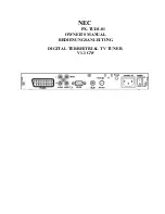
ANT LOOP SWITCH
Adjusts the MR66 circuit to match the
particular type of AM antenna used. ANT
position is for a conventional antenna,
usually of the outdoor type, from 50 to 150
feet in length. LOOP position is for the short
loop antenna supplied with the MR66.
LAMPS SWITCH
Provides bright (HI) or dim (LO) front
panel lighting.
AC OUTLET
Provides 117 volt AC power up to 350
watts maximum for additional equipment
such as turntables or other tuners. This out-
let is not fused and turns on and off with the
front panel MODE SELECTOR switch.
FUSE
1 amp Slo-Blo type fuse to protect the
tuner circuit. This fuse does not operate on
the AC outlet.
FM ANT
Terminals for connecting an FM antenna
to the MR66.
TO TV SET
Terminals for connecting TV set antenna
leads when a VHF TV antenna is used for
both the MR66 and the TV set. The antenna
is automatically switched to the MR66 when
the MODE SELECTOR turns the MR66 ON.
The antenna is switched back to the TV set
when the MODE SELECTOR is turned to
POWER OFF.
STEREO-MON OUTPUTS
1 and 2 output jacks supply tuner signals
of the correct value to connect to tuner inputs
or auxiliary inputs of a control preamplifier.
The front panel MODE SELECTOR switch pro-
vides stereo AM-FM at jacks 1 and 2, re-
spectively; monophonic FM at "both" jacks
1 and 2; or monophonic AM at "both" jacks
1 and 2.
AM FM OUTPUTS
AM signals are present at the AM jack and
FM signals are present at the FM jack at all
times the tuner is operating, regardless of
the MODE SELECTOR switch setting. The
AM function switch and the FM function
switch affect the signals at these output
jacks. Use these jacks to connect the tuner
to remote amplifiers, apart from the main
sound system.
AM OUTPUT LEVEL CONTROL
Adjusts the volume level of the AM output.
See section titled "ADJUSTMENTS."
FM OUTPUT LEVEL CONTROL
Adjusts the volume level of the FM out-
put. See section titled "ADJUSTMENTS."
INSTALLATION
The Mclntosh MR66 tuner may be in-
stalled on a table, on a shelf, in a custom
built-in cabinet or in a professional equip-
ment rack. For best appearance in an open
installation, it is suggested that you mount
the MR66 in the attractive Mclntosh Model
L66 finished wood cabinet.
The MR66 may be mounted in panels up
to 1 inch in thickness. If the panel is at least
¼ inch in thickness, the tuner will be ade-
quately supported by the four front panel
mounting screws. In cases where the front
panel may be thin or flexible, a shelf is neces-
sary to support the weight of the tuner. A
shelf is not required when the MR66 is
mounted in a metal rack panel.
An MR66 cabinet installation should pro-
vide at least 13% inches behind the mount-
ing panel for clearance of leads and con-
nectors. Allow inside dimensions of at least
16½ inches in width and 5 inches in height
for adequate air circulation. The back panel
of the MR66 cabinet should be left as open as
possible for best ventilation. Avoid mounting
the tuner directly over a power amplifier. The
heat from the amplifier output tubes may
affect the precision tuner calibration. Ade-
quate ventilation will insure your tuner a long
and trouble-free life.
6
Содержание MR66
Страница 2: ......
Страница 17: ...AM STATION LOG STATION DIAL FREQ LOG SCALE LOCATION CITY STATE ANTENNA DIRECTION REMARKS MONO STEREO TIME DATE ...
Страница 18: ...FM STATION LOG STATION DIAL FREQ LOG SCALE LOCATION CITY STATE ANTENNA DIRECTION REMARKS MONO STEREO TIME DATE ...
Страница 19: ......


