


INSTALLATION
allowing it to slide into the shelves. When the unit has been positioned completely into the
cabinet and its front panel is against the cabinet panel, it can be locked into position. Turn
each PANLOC button approximately one-quarter turn clockwise to lock. Turn the PANLOC button
one-quarter turn counterclockwise to unlock the unit so it can be removed from the cabinet.
UNPACKING
Open the carton and remove the PANLOC shelves, the hardware package and the mount-
ing template. Lift the amplifier up off the shipping pallet and remove the plastic bag. The
amplifier is now ready for shelf or table top installation.
If the amplifier is to be installed in a Mclntosh cabinet or custom installation, place it carefully
upside-down on a flat surface and unscrew the four plastic feet from the bottom of the amplifier
chassis.
INSTALLING IN A McINTOSH CABINET
Guide the amplifier AC power cord through the front panel opening to the back of the cabinet.
Slide the amplifier into the opening, making sure the rails on the bottom of each side of the
amplifier chassis engage the tracks on the PANLOC shelves. Slide the amplifier completely
into the cabinet until the back side of its front panel is pressing gently against the front of
the cabinet panel. Turn the PANLOC buttons approximately one-quarter turn clockwise to lock
the amplifier into the cabinet. Turn the buttons one-quarter turn counterclockwise to unlock
and remove the amplifier.
CUSTOM INSTALLATION
1. MARK THE CABINET FRONT PANEL
Tape the plastic mounting template to the cabinet panel in the position where the amplifier
is to be mounted. The broken lines that represent the outline of the rectangular cutout also
represent the outside dimensions of the amplifier chassis. Make sure these lines clear any
shelves, partitions or any other equipment mounted in the same cabinet. With the template
in place, first mark the six A and B holes, and the four small holes that locate the corners
of the cutout. Then join the four corner markings with a ruler or straightedge.
2. DRILL THE HOLES
Use a drill with a 3/16 inch (5mm) bit. Drill perpendicular to the front panel the six A and
B holes. Then, using a drill bit slightly larger than the tip of your saw blade, drill one hole at
each of two diagonally opposite corners. The holes should barely touch the inside edge of the
penciled outline. Before taking the next step, be sure the six A and B holes have been drilled.
6
Содержание MC7100
Страница 1: ...MC7100 POWER AMPLIFIER ...
Страница 2: ......
Страница 3: ...MC7100 POWER AMPLIFIER ...
Страница 14: ...PERFORMANCE CHARTS 12 ...
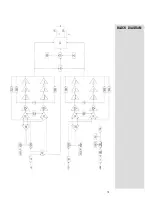
Страница 17: ...BLOCK DIAGRAM 15 ...
Страница 18: ...039942 ...
Страница 19: ......
Страница 20: ......


