background image

12

TILLER

TO ADJUST HANDLE HEIGHT (See Fig. 15)

Factory assembly has provided lowest handle height.  Se lect 

handle height best suited for your tilling conditions.  Handle 

height will be different when tiller digs into soil.
•  If a higher handle height is desired, loosen the four 

nuts securing handle panel to engine brackets.

•  Slide handle panel to desired location.
•  Tighten the four nuts securely.

HANDLE

PANEL

ENGINE BRACKETS

NUTS (ALSO 2

ON LEFT SIDE

OF TILLER)

Fig. 15

SERVICE AND ADJUSTMENTS

CAUTION:  Disconnect spark plug wire from spark plug and place wire where it cannot come into 

contact with plug.

Fig. 16

Fig. 17

MAINTENANCE

MUFFLER

Do not operate tiller without muffler. Do not tamper with 

exhaust system. Damaged mufflers or spark arresters could 

create a fire hazard. Inspect pe ri odi cally and re place if 

nec es sary. If your engine is equipped with a spark arrester 

screen assembly, re move every 50 hours for cleaning and 

inspection. Re place if dam aged.

SPARK PLUG

Replace spark plugs at the beginning of each tilling sea-

 son or after every 50 hours of use, whichever comes first.  

Spark plug type and gap setting are shown in “PROD UCT 

SPEC I FI CA TIONS” on page 3 of this manual.

TRANSMISSION

Your transmission is sealed and will not require lubrication 

unless serviced.

CLEANING

Do not clean your tiller when the engine and transmission 

are hot.  We do not rec om mend using pressurized water 

(gar den hose, etc.) to clean your unit un less the gasket 

area around the trans mis sion and the engine muf fler, air 

fil ter and car bu re tor are cov ered to keep wa ter out.  Wa ter 

in en gine will short en the useful life of your tiller. 
•  Clean engine, wheels, finish, etc. of all foreign matter.
• 

Keep finished surfaces and wheels free of all gas o line, 

oil, etc.

•  Protect painted surfaces with au to mo tive type wax.

TINE ARRANGEMENT

Your outer tines can be assembled in several different ways 

to suit your tilling or cultivating needs.

CAUTION:  Tines are sharp.  Wear 

gloves or other protection when han-

 dling tines.

tine_4

OUTER 

TINE

INNER TINE

HAIRPIN CLIP

A

B

A

B

CLEVIS

PIN 

MID-WIDTH TILLING - 24" PATH (See Fig. 17)

•  Assemble holes “A” in tine hubs to holes “C” in tine 

shaft.

tine_5

A

C

A

C

NORMAL TILLING - 26" PATH (See Fig. 16) 

•  Assemble holes “A” in tine hubs to holes “B” in tine 

shaft.

Содержание 532 43 36-95

Страница 1: ...532 43 36 95 MHDF800 Operator s Manual...

Страница 2: ...ever allow adults to operate the equipment without proper instruction Keep the area of operation clear of all persons par ticularly small children and pets PREPARATION Thoroughly inspect the area wher...

Страница 3: ...AND SHOULD NOT BE USED ON OR NEAR ANY UNIMPROVED FOREST COVERED BRUSH COVERED OR GRASS COVERED LAND UNLESS THE ENGINE S EXHAUST SYSTEM IS EQUIPPED WITH A SPARK ARRESTER MEETING APPLICABLE LOCAL LAWS...

Страница 4: ...proper operation of your tiller all parts and hardware you assemble must be tightened securely Use the correct tools as necessary to insure proper tightness TOOLS REQUIRED FOR ASSEMBLY A socket wrench...

Страница 5: ...UT A ENGINE BRACKET HALVES Fig 3 STAKE SPRING TILLER HANDLES 02 05 1 CABLE S Fig 2 4 ANDLE 0ANEL HANDLE PANEL BOLTS FLAT WASHER HEX BOLT 5 16 18X1 TILLER HANDLE HANDLE PANEL NUT LOCK WASHER HEX BOLT 5...

Страница 6: ...mean ing RECOIL STARTER HANDLE DEPTH STAKE TINE SHIELD CHOKE CONTROL FORWARD TINE CONTROL TINES THROTTLE CONTROL Fig 4 MEETS ANSI SAFETY REQUIREMENTS Our tillers conform to the safety standards of the...

Страница 7: ...ase reverse tine control to stop reverse move ment ENGINE Move throttle control to STOP position Never use choke to stop engine TILLING The speed and depth of tilling is regulated by the position of t...

Страница 8: ...rope out slowly until engine reaches start of compression cycle rope will pull slightly harder at this point Pull recoil starter handle quickly Do not let starter handle snap back against starter If e...

Страница 9: ...rdsoilwhichmaycontribute to excessive bounce and difficult handling of your tiller Hard soil should be moistened before tilling however extremely wet soil will ball up or clump during tilling Wait unt...

Страница 10: ...CONTROL c IDLER ARM GENERAL RECOMMENDATIONS The warranty on this tiller does not cover items that have beensubjectedtooperatorabuseornegligence Toreceive fullvaluefromthewarranty theoperatormustmainta...

Страница 11: ...alent Tighten oil filler plug securely each time you check the oil level TO CHANGE ENGINE OIL See Figs 11 and 12 Determine temperature range expected before oil change All oil must meet API service cl...

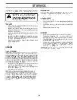
Страница 12: ...ea son or after every 50 hours of use whichever comes first Spark plug type and gap setting are shown in PRODUCT SPECIFICATIONS on page 3 of this manual TRANSMISSION Your transmission is sealed and wi...

Страница 13: ...htinecontrol ON helddowntohandle pushdown on handle to raise tines off the ground Slowly pull recoil starter handle while observing tines Tines should rotate forward If tines do not rotate inner wire...

Страница 14: ...NGINE ABOVE THE FACTORY HIGH SPEED SETTING CAN BE DANGEROUS IF YOU THINK THE ENGINE GOVERNED HIGH SPEED NEEDS ADJUSTING CONTACTYOURNEARESTAUTHORIZEDSERVICECENTER DEPARTMENT WHICH HAS THE PROPER EQUIPM...

Страница 15: ...eplace belts if necessary See belt re placement instructions in the Service and Adjustments section of this manual Lubricate as shown in the Maintenance section of this manual Be sure that all nuts bo...

Страница 16: ...6 Stale or dirty fuel 6 Empty fuel tank and refill with fresh gasoline 7 Water in fuel 7 Empty fuel tank and carburetor and refill tank with fresh gasoline 8 Clogged fuel tank 8 Remove fuel tank and...

Страница 17: ...17 SERVICE NOTES...

Страница 18: ...bled adjusted operated and main tained in accordance with the instructions furnished This Warranty does not apply to any product which has been subjected to alteration misuse abuse improper assembly o...

Отзывы: