- 1 -
SAFET Y INFORMATION
Introduction
This Safety Alert Symbol is used to call attention
to items or operations which may be dangerous
to those operating or working with this equipment.
The symbol can be found throughout this manual
and on the unit. Please read these warnings and cautions,
along with all decals, carefully before attempting to operate
the unit. Make sure every individual who operates or works
with this equipment is familiar with all safety precautions.
WARNING
GENERAL WARNING. Indicates information
important to the proper operation of the equipment.
Failure to observe may result in damage to the
equipment and/or severe bodily injury or death.
CAUTION
GENERAL CAUTION. Indicates information
important to the proper operation of the equipment.
Failure to observe may result in damage to the
equipment.
Safety Precautions
LETHAL EXHAUST GAS:
An internal
combustion engine discharges carbon
monoxide, a poisonous, odorless, invisible
gas. Death or serious illness may result if
inhaled. Operate only in a properly ventilated
area. NEVER OPERATE IN A CONFINED
AREA!
DANGEROUS FUELS:
Use extreme caution
when storing, handling and using fuels, as
they are highly volatile and explosive in vapor
state. Do not add fuel while engine is running.
Stop and cool the engine before adding fuel.
DO NOT SMOKE!
SAFETY GUARDS:
It is the owner's
responsibility to ensure that all guards and
shields are in place and in working order.
IGNITION SYSTEMS:
Breakerless, magneto,
and battery ignition systems can cause severe
electrical shocks. Avoid contacting these units
or their wiring.
SAFE DRESS:
Do not wear loose clothing,
rings, wristwatches, etc. near machinery.
NOISE PROTECTION:
Wear OSHA specified
hearing protection devices.
EYE PROTECTION:
Wear OSHA specified
eye shields, safety glasses, and sweat bands.
FOOT PROTECTION:
Wear OSHA specified
steel-tipped safety shoes.
HEAD PROTECTION:
Wear OSHA specified
safety helmets.
OPERATOR:
Keep children and bystanders
off and away from the equipment.
DUST PROTECTION
:
Machining, crushing or
handling of stone, concrete, masonry, metal
and other materials may generate dust, mist
and fumes containing chemicals such as
silica, known to cause serious or fatal injury or illness, such
as respiratory disease, silicosis, cancer, birth defects, or
other reproductive harm.
• Control dust, mist and fumes at the source where possible.
Water should be used to control dust whenever feasible.
• Use good work practices and follow the recommendations
of the manufacture, OSHA/NIOSH and other occupational
trade associations.
• When hazards cannot be eliminated the operator and any
bystanders should always wear a OSHA specified respirator
for materials being handled.
REFERENCES:
For details on safety rules and regulations
in the United States, contact your local Occupational Safety
and Health Administration (OSHA) office. Equipment
operated in other countries must be operated and serviced
in accordance and compliance with any and all safety
requirements of that country. The publication of these safety
precautions is done for your information. MBW does not by
the publication of these precautions, imply or in any way
represent that these are the sum of all dangers present near
MBW equipment. If you are operating MBW equipment, it is
your responsibility to insure that such operation is in full
accordance with all applicable safety requirements and
codes. All requirements of the United States Federal
Occupational Safety and Health Administration Act must be
met when operated in areas that are under the jurisdiction
of that United States Department.
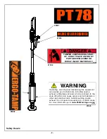
Safety Decals
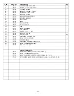
Carefully read and follow all safety decals. Keep them in
good condition. If decals become damaged, replace as
required. If repainting the unit, replace all decals. Decals are
available from authorized MBW distributors. Order the decal
set listed on the following page(s).
Содержание ERGO-TAMP
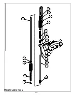
Страница 13: ...10 Handle Assembly...
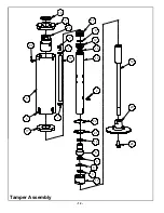
Страница 15: ...12 Tamper Assembly...


