- 8 -
8.
With body (#10) out of outer shroud (#6), remove
retaining ring (#19) from cap (#13) and then slide
upper shroud cover off (#7).
9.
Loosen hose camps (#1) from air hose (#18) and
then remove air hose from elbows (#2).
10. Using a metal rod placed through holes in the Tamper
body (#10) unscrew cap (#13).
11. Separate valve upper (#11), lower (#12), o-ring (#16),
and valve disc (#9) from cap (#13) (Note: Inspect
components for wear and replace if necessary).
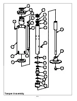
Tamper Assembly
Refer to Tamper Assembly, page 12.
1.
Place new o-ring (#16) on to lower valve (#12).
2.
Assemble upper valve (#12) lower valve (#13), and
valve disc (#9), then insert into cap (#13). (Note:
Make sure valve disc (#9) stays seated).
3.
Using medium-strength thread locking compound,
along with a metal rod placed through holes in
Tamper body (#10), screw cap (#13) over valve
assembly onto body (#10).
4.
Install air hose (#18) onto hose elbow (#2) and
secure using hose camps (#1).
5.
Using retaining ring (#19) secure upper shroud cover
(#7) to Tamper cap (#13).
6.
Slide outer shroud cover (#6) up from bottom and
connect to upper shroud cover (#7). Secure with four
screws (#20).
7.
Feed lower shroud (#17) into shroud cover (#6) and
secure with four screws (#20).
8.
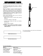
Place new o-ring (#16) onto bushing support (#8) and
seal set (#4) into bushing support (#8) (Note:
Position seal set as shown below).
9.
Install new shaft wiper (#3) and shim (#5) into bottom
cap (#15).
10. Lubricate head of shaft assembly (#14) with air tool
oil and slide into body (#10)
11. Position retaining ring (#22) and locking ring (#21)
over bottom of tamper body.
12. Using air tool oil on bushing support (#8) feed support
into Tamper body (#10) and hand tighten bottom cap
(#15).
13. Secure bottom cap (#15) into position with locking
ring and retaining ring. (Note: Check ease of shaft
(#14) movement. If bottom cap (#17) is to tight shaft
movement will be difficult).
14. Using medium-strength thread locking compound on
bolt (#24) secure foot (#23) to shaft (#14). Torque to
80 ft lb. NOTE: To ensure proper tightening of
ergotamp shoe, retorque after first 15 minutes or
operation.
Handle Replacement Cycles and Tolerances
Tamper Replacement Cycles and Tolerances
6($/6(732,17
72:$5'6)227
/$5*(676($/
/2&$7('21%27720
Bushings
When bearing material has significant wear
Seal and Wiper
When air leakage occurs
Springs
When significant wear is noticed
Tube
When inside of tube becomes scoured or galled
Shaft
When shaft become bent or surface becomes scratched
Shaft
If shaft is bent it needs to be replaced
Содержание ERGO-TAMP
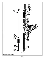
Страница 13: ...10 Handle Assembly...
Страница 15: ...12 Tamper Assembly...


