


Video Intercom Door Station
·
·
·
·
User Manual
68
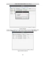
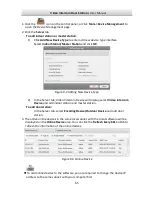
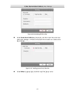
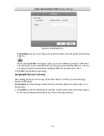
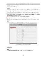
If the window with import file button, key importing mode drop-down list, password
and confirm password field pops up, follow the steps below to reset the password:
This option is available to door stations.
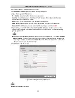
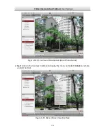
Figure 9-6
Resetting Password (Option 1)
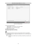
1.
Click
Export
to save the device file on your computer.
2.
Send the file to our technical engineers.
3.
Our technical engineer will send you a file to you. After receiving a file from the
technical engineer, select
Import File
from Key Importing Mode drop-down list and
click
to import the file.
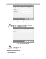
4.
Input new password in text fields of
Password
and
Confirm Password
.
5.
Click
OK
to reset the password.
STRONG PASSWORD RECOMMENDED
– We highly recommend you create a strong
password of your own choosing (Using a minimum of 8 characters,
including at least three of the following categories: upper case letters,
lower case letters, numbers, and special characters.) in order to
increase the security of your product. And we recommend you reset
your password regularly, especially in the high security system,
resetting the password monthly or weekly can better protect your product.
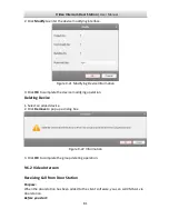
Option 2: