background image


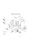
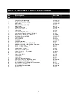
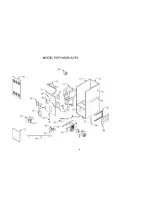
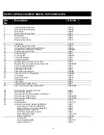
PARTS LISTING: HIGHBOY MODEL: POF1HD091AVFA 


Ref. 
No. 

Description 

Part No. 


Left Side Panel Assembly 

29187L 


Right Side Panel Assembly 

29186L 


3 Rear 

Panel 

29205L 


Blower Division Assembly 

29189 


5 Base 

Panel 

26216 


Inner Front Panel 

30066 


Blower Access Panel 

27721L 


8 Top 

Panel 

21437L 


Heat Exchanger Assembly 

28675 


10 

Combustion Chamber Retainer Bracket 

27068 


11 

Replacement Combustion Chamber 

27000WP 


12 

Oil Burner Mounting Plate 

29869 


13 

Flue Connector  

29005 


14 Pouch 

Gasket 

2080175 


15 

Flue Collar Gasket  

21994 


16 Insulation 

Retainer 

20602 


17 

Radiator Clean-out Cover (2 per unit) 

29162 


17 
18 
18 

Radiator Clean-out Cover Gasket (2 per unit) 
Clean-out Gasket Retainer 
Clean-out Tube Gasket 

240006333 
29161 
29163 


19 

Filter Frame 16” X 25” 

18020 


20 

Filter Frame End Support 

5592B2 


21 

Filter 16” X 25” X 1” Permanent 

2180023 


24 Control 

Box 

29362 


25 

Upper Door Panel 

30164L 


 Logo 

Bezel 

28479 


 Logo 

Label 

28563 


26 

Limit Disc 60T11 BOF 155

°

30071  

27 

Fan Timer Control 1168-1 ECM UTEC 

240007048 


28 

Wire Harness, Controls Fan Timer 

29364 


29 

Wire Harness, Blower 

29365 


30 
31 
31 

Wire Harness, Fan Timer Board, Transformer 
Wire Harness, ECM Control 
Wire Harness, ECM Supply 

29751 
240006438 
240005742 


32 Transformer 

27738 


33 

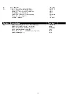
Draft Regulator 

27494 (5”) 


34 

Oil Burner Assembly, Beckett AF76BNHS 

30067 
29689  

     Burner Motor 1/7 HP 3450 RPM PSC 
     Beckett Clean-cut Oil Pump A2EA6520 

29688 


     Solid State Ignitor 10SAY-01 

29522 


     Oil Primary Combustion Control  

29664 


     Flame Retention Head  
     Nozzle, 0.65/80ºA   

11961 (F3)  
210086 


     Low Fire Kit 
     Low Firing Rate Baffle 
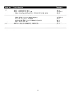
     Nozzle, 0.50/80° A 

29880 
25521101 
29389 


34

Содержание POF1HD091AVFA

Страница 1: ...Do not store or use gasoline or other flammable liquids or vapors in the vicinity of this or any other appliance ALL INSTALLATIONS MUST MEET ALL LOCAL PROVINCIAL STATE AND FEDERAL CODES WHICH MAY DIF...

Страница 2: ...NER PRIMARY SAFETY CONTROL 6 18 COMBUSTION CHAMBER 6 19 CIRCULATING AIR BLOWER 7 19B CIRCULATING AIR BLOWER 7 20 MAINTENANCE AND SERVICE 8 21 OPERATING INSTRUCTIONS 8 22 ECM BLOWER MOTOR OPERATION 9 A...

Страница 3: ...rdance with local codes Regulations prescribed in the National Codes and Local regulations take precedence over the general instructions provided on this installation manual When in doubt please consu...

Страница 4: ...windows or where basement windows are well sealed a permanent opening communicating with a well ventilated attic or with the outdoors shall be provided using a duct if necessary The duct opening shall...

Страница 5: ...similar device The power requirement for the POF1HD140AVFA and POF1HD091AVFA models is 120 VAC 1 60 Hz 12A Accessories requiring 120 VAC power sources such as electronic air cleaners and humidifier t...

Страница 6: ...trace smoke spot on the Bacharach Scale BEFORE OPERATING THE FURNACE CHECK BURNER ALIGNMENT WITH COMBUSTION CHAMBER THE END CONE OF THE AIR TUBE MUST BE CENTRED TO THE ACCOMODATING RING PROVIDED IN TH...

Страница 7: ...er sized duct systems may require a higher blower speed to obtain a reasonable system temperature rise Some older duct systems were not designed to provide static pressure They typically feature speci...

Страница 8: ...ace or burner It is advisable to change the oil burner nozzle and oil filter on an annual basis The venting system should be cleaned and inspected for signs of deterioration Replace pitted or perforat...

Страница 9: ...POUR OR WHEN THE COMBUSTION CHAMBER IS VERY HOT NEVER BURN GARBAGE OR PAPER IN THE FURNACE AND NEVER LEAVE PAPER OR RAGS AROUND THE UNIT Soft Stop At the end of the heating cycle the ECM variable spee...

Страница 10: ...usgph F3 3 in POF1HD105AVFA 87 000 AF76BNHS 0 75 80 A 100 psig 0 75 usgph F3 3 in 1 Head is shielded by ceramic insulator 2 Low Firing Rate Baffle required when using a 0 50 gallon nozzle Bold models...

Страница 11: ...16 inch Older instruction sheets specify 7 16 inch The current specification is 5 16 inch Distance ahead of nozzle 1 16 inch Z dimension the distance from the front of the end cone head to the face of...

Страница 12: ...8 inches w c 0 5 inches w c POF1HD105AVFA POF1HD119AVFA POF1HD140AVFA 100 10 DD 1 2 HP ECM 7 7 70 F 500 700 1100 1525 600 1400 CFM RANGE Continuous Heating Cooling Furnace Model Blower Motor HP Motor...

Страница 13: ...ions Inches Cabinet Plenum Openings Filter Return Furnace Model Width Depth Height Supply Side Bottom Flue Diameter Type Size Shipping Weight POF1HD140AVFA 22 30 3 4 58 20 x 20 14 x 22 14 x 22 6 Perma...

Страница 14: ...ns Inches Cabinet Plenum Openings Filter Return Furnace Model Width Depth Height Supply Side Bottom Flue Diameter Type Size Shipping Weight POF1HD091AVFA 22 30 3 4 49 5 8 20 x 20 14 x 22 14 x 22 5 Per...

Страница 15: ...F ON C 2 ON ON D 0 50 ON ON D 1 5 SW3 ADJUST SW4 DELAY DIP Switch Position CFM DIP Switch Position INPUT 1 2 POS 1 2 POS USGPH OFF OFF A 0 OFF OFF A 0 65 ON OFF B 15 ON OFF B N A OFF ON C 15 OFF ON C...

Страница 16: ...equal to 400 CFM SW3 ADJUST Heating Mode Increase OR decrease temperature rise respectively Cooling Mode Increase OR decrease CFM respectively INPUT DIP Switch Position AC Size 1 2 POS USGPH 1 2 POS T...

Страница 17: ...a basse vitesse si quipp e AL limite auxiliaire si quipp e REQUIRED FOR CANADIAN INSTALLATIONS BLOCKED VENT SAFETY L BVS RIELLO 40F BURNER br leur BECKETT AF BURNER br leur 4 1 2 3 OR BK WH VI N L 530...

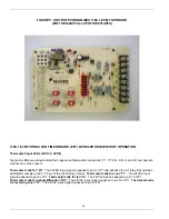
Страница 18: ...adjustments can be made by moving the dipswitch settings on the timer control board for fan off delay To check the operation of the limit switch shut off power to the furnace Temporarily remove the n...

Страница 19: ...spark for 10 sec a Provides continuous spark after flame is sensed to assure that burner remains lit b Turns on LED diagnostic light c Starts carryover timer i Flame and call for heat are monitored I...

Страница 20: ...present Thermostat calls for W The 24VAC input signal is passed to pin 2 of P1 and will drive the K1 relay that provides dedicated contacts to the T T input of the Oil Primary Control Thermostat calls...

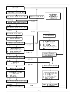
Страница 21: ...URNS TO IDLE STATE FLAME FLAME FLAME FLAME NO FLAME NO FLAME FLAME LOST FLAME LOST REMAINS IN IDLE STATE OIL PRIMARY CONTROL SEQUENCE of OPERATION LOCKOUT STATE OIL PRIMARY CONTROL Shuts off burner mo...

Страница 22: ...sing the reset button The LED diagnostic light will flash the following code Table C 2 Cad Cell Resistance Flashes Resistance in Ohms 1 Less than 400 2 Between 400 800 3 Between 800 1600 4 Between 160...

Страница 23: ...ad cell with new cad cell and recheck If indicator light does not turn off remove yellow lead wires from oil primary control and recheck If indicator light is still on replace the oil primary control...

Страница 24: ...Step 7 6 Reset oil primary control by pushing in and releasing red reset button Indicator light continues to flash at 1 Hz rate Verify that the control is not in restricted mode See notes at end of th...

Страница 25: ...ero each time a call for heat is successfully completed To reset from RESTRICTED MODE press and hold the reset button for 30 seconds When the LED flashes twice the device has reset NOTE Disable functi...

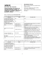
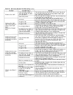
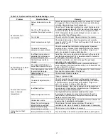
Страница 26: ...aximum of 1500 in the presence of light Ensure that room light is not leaking into the cad cell compartment See diagnostic light section No fuel oil Check fuel oil supply Check that all hand operated...

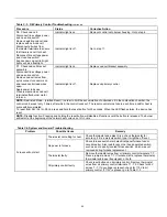
Страница 27: ...radiator Poor alignment between oil burner blast tube and fire pot Check alignment Blast tube should be centered with fire pot burner opening Oil burner head should be inch back from the inside surfac...

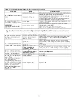
Страница 28: ...y joints and seams Insulate ductwork if necessary FINAL CHECK OUT 3 Where the oil shut off valve from the oil storage tank is located ENSURE THAT ALL SAFETY DEVICES AND ELECTRICAL COMPONENTS HAVE BEEN...

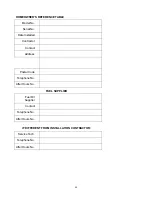
Страница 29: ...al No Date Installed Contractor Contact Address Postal Code Telephone No After Hours No FUEL SUPPLIER Fuel Oil Supplier Contact Telephone No After Hours No IF DIFFERENT FROM INSTALLATION CONTRACTOR Se...

Страница 30: ...30...

Страница 31: ...sket 2080175 15 Air Baffle 109007733 16 Insulation Retainer 20602 17 Radiator Clean out Cover 2 per unit 29162 17 18 18 Radiator Clean out Cover Gasket 2 per unit Clean out Gasket Retainer Clean out T...

Страница 32: ...il Primary Combustion Control Genisys 240007858 Flame Retention Head F6 Nozzle 1 00 60 W 11961 14619329 Ref No Description Part No 35a Blower Assembly Direct Drive 3 Ton ECM Motor 109007723 Blower Hou...

Страница 33: ...33...

Страница 34: ...Tube Gasket 240006333 29161 29163 19 Filter Frame 16 X 25 18020 20 Filter Frame End Support 5592B2 21 Filter 16 X 25 X 1 Permanent 2180023 24 Control Box 29362 25 Upper Door Panel 30164L Logo Bezel 28...

Страница 35: ...ECM 30146 109007271 Blower Housing and Wheel 100 10T DD POF1HD091AVFA 30626 Blower Motor 1 2 hp ECM Programmed 109007272 Motor Mounting Band TR6884B 17811 Motor Mount Arms 10 10 DD Blower 3 per unit 2...

Страница 36: ...NOTES Nordyne Inc 8000 Phoenix Parkway O Fallon Missouri 63368 766B 0909...

Отзывы: