


Installation and Operational Instructions for
ROBATIC
®
-clutch Type 540.1 _ _
Sizes 3 – 9
(B.5.1.GB)
08/10/2010 TK/KE/GC/SU
Chr. Mayr GmbH + Co. KG
Tel.: 08341 / 804-0
Eichenstraße 1
Fax: 08341 / 804-421
D-87665 Mauerstetten
http://www.mayr.de
Page 9 of 10
Germany
E-Mail:
Installation of Type 540.100 (Fig. 1)
1.
Press the deep groove ball bearing (4) onto the outer ring in
the coil carrier (3) and secure using the locking ring (5).
2.
Press the coil carrier (3) inc. the deep groove ball bearing
(4) onto the bearing inner ring up to the rotor (1) contact.
Align it axially backlash-free with the shim rings (6 and 7)
and secure using the locking ring (8).
Installation of Type 540.140 (Fig. 2)
1. Press the deep groove ball bearing (4) onto the outer ring in
the coil carrier (3) and secure using the locking ring (5).
2. Press the coil carrier (3) inc. the deep groove ball bearing
(4) on the bearing inner ring up to contact onto the rotor (2).
Align it axially backlash-free with the shim rings (6 and 7)
and secure using the locking ring (8).
3. a) Sizes 3 to 6:
Press the first deep groove ball bearing (11) on the outer
ring into the driver flange (10) and insert a shim ring (21);
press the second deep groove ball bearing (11) on the outer
ring into the driver flange (10), align it axially backlash-free
with the shim rings (12, 13) and secure using the locking
ring (14).
b) Sizes 7 to 9:
Insert the ball bearing compensation disk (20) and then a
shim ring 0,5 mm (22) into the driver flange (10); insert the
first deep groove ball bearing (11) into the driver flange (10)
by hand (making sure that it moves easily). Then insert the
shim ring 0,5 mm (17) aligning to the ball bearing inner ring
and insert the second deep groove ball bearing (11) into the
driver flange (10) by hand (making sure that it moves easily).
Bring the deep groove ball bearing into position using an
installation device against the force of the ball bearing
compensation disk (20) (0,3 - 0,6 mm before the
compensation disk blocks), align it axially with the shim rings
(12, 13) and secure using the locking ring (14).
4. Mount the armature disk assembly (9) onto the driver flange
(10) and align it to a radial run-out of max. 0,15 mm.
Exception => Size 6:
Position the calculated shim rings (15) on the
ball bearing inner ring (11) before installing the
armature disk (9) onto the driver flange (10).
5. Tighten the cap screws (Item 19 with spring washer).
Secure the screws with Loctite 243 and observe the
tightening torque acc. Table 1!
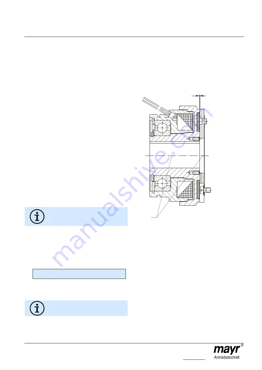
6. Measure dimension "A" (= armature disk friction surface to
bearing inner ring, see Fig. 2).
7. Measure dimension "B" (= rotor friction surface to bearing
contact on collar, see Fig. 2).
8. Calculate the shim ring dimension:
9. Mount the calculated shim rings (15) onto the rotor (2).
Press the driver flange (Item 10 on the bearing inner ring)
onto the rotor (2). Align it axially backlash-free with the shim
rings (16 and 17) and secure using the locking ring (18).
Not valid for Size 6, see point 4.
10. Check dimension "a" (acc. Table 1) and correct it if
necessary by removing or adding shim rings (15).
Clutch Installation
The mounting components, such as the shafts or flanges, are to
be mounted and secured so that no axial backlash is possible
and so that the specified dimension "a" (air gap between the
rotor (1 or 2) and the armature disk (9)) acc. Table 1 is
maintained.
Axial backlash on the mounting components alters dimension "a"
and can lead to the rotor (1 or 2) rubbing against the armature
disk (9). Additionally, please observe the permitted centre offset
"V" of the mounted components on Type 540.100 (see Fig. 6 and
Table 1).
Fig. 6
Electrical Connection
The clutch coil is connected to a DC voltage supply.
The voltage value is stated on the Type tag.
Maintenance and Checks
Please check the air gap "a" and the permitted centre offsets "V"
acc. Table 1 at regular intervals.
Bearing backlash and wear on the friction surfaces alter the
permitted Table values. Apart from this, ROBATIC
®
-clutches are
maintenance-free.
Shim ring dimension (15) = "A" + "a" (Table 1) - "B"
a
V


