


Installation and Operational Instructions for
ROBA
®
-quick Type 520.1_ _ and Type 520.2_ _.0
Sizes 3 to 9
(B.5.2.EN)
26/08/2013 TK/RB/SU
Chr. Mayr GmbH + Co.
KG
Eichenstraße 1, D-87665 Mauerstetten, Germany
Tel.: +49 8341 804-0, Fax: +49 8341 804-421
Page 6 of 9
Scope of Delivery / State of Delivery
Please check the scope of delivery according to the Parts List as
well as the state of delivery immediately after receiving the
goods.
mayr
®
will grant no guarantee for belated complaints.
Please report transport damage immediately to the deliverer.
Please report incomplete delivery and obvious defects
immediately to the manufacturer.
Function
ROBA
®
-quick brakes
are “energised to engage”, electromagnetic
pole face brakes.
When DC voltage is applied to the magnetic coil in the coil
carrier (1), a magnetic field is built up. The armature disk (2) is
attracted to the coil carrier (1).
The braking torque is transmitted by friction between armature
disk (2) and the iron poles and the friction lining surfaces of the
coil carrier (1). The coil carrier (1) is screwed onto the machine
wall and centred on the shaft bearing, see Figs. 2 and 3 on
page 7.
The air gap “a“ is defined via a distance ring between the shaft
bearing and the drive element (Fig. 2) or inner hub (Fig. 3).
In new condition, torque transmission first takes
place via the metal outer pole on the coil carrier
(1) and, after a short operation period, then
additionally via the inner pole.
After the entire run-in procedure, an even
frictional combination occurs on the metal poles
and on the friction lining (1.2) lying between
them.
The full transmittable nominal torque is not
achieved until after the run-in procedure has
been carried out as described below.
Design
ROBA
®
-quick brakes have Electrical Protection IP 54 and
Insulation Material Class F (up to 155 °C) for coil, casting
compound and connection strands.
On the design with a connection terminal, the connection
terminal itself corresponds to Protection IP 00.
The surfaces on the coil carrier (1) and flange hub (5) are
phosphated, the armature disk (2) is gas nitro-carburized or
plasma-nitrided (friction surfaces are ground), and the
transmission spring is made of stainless steel.
The drive elements should be made from a material which is a
poor magnetic conductor in order to prevent magnetic loss due
to leaking flux and therefore loss of force.
Explanation of Terms
The
nominal torque M
2
is the largest transmittable torque (after
run-in has been completed), with which the closed brake can be
loaded without slipping occurring.
The
relative duty cycle
is the ratio of duty cycle to cycle time in
percent (% duty cycle).
Torque Characteristics
In new condition, approx. 50 % of the catalogue nominal
torque (M
2
) is transmitted.
The components reach the catalogue nominal torque when the
friction surfaces are run in. As a rough guideline value, approx.
100
– 200 switchings in dynamic operation, a typical speed
(approx. 500 to 1000 rpm) and a medium friction work (see
Table 2) can be given.
Longer slipping of the brake is to be avoided, especially at low
speeds, as this can cause scoring formation and therefore
damage to the friction surfaces.
Brakes used in static or virtually static operation do not reach the
nominal torque (M
2
) stated in the Technical Data.
If requested, the brakes can also be run in at the place of
manufacture. For this, please ensure exact installation customer-
side according to the specifications in order to reproduce the
friction conditions as precisely as possible. At the same time, the
“friction carbon” produced must not be rubbed off.
If the brakes are run in to the nominal torque at the place of
manufacture and then operated in static or virtually static mode,
please allow for a drop to approx. 60
– 70 % of the nominal
torque. This is the case if the brake falls bellow the speed or
friction work (Q
a
) stated in Table 2.
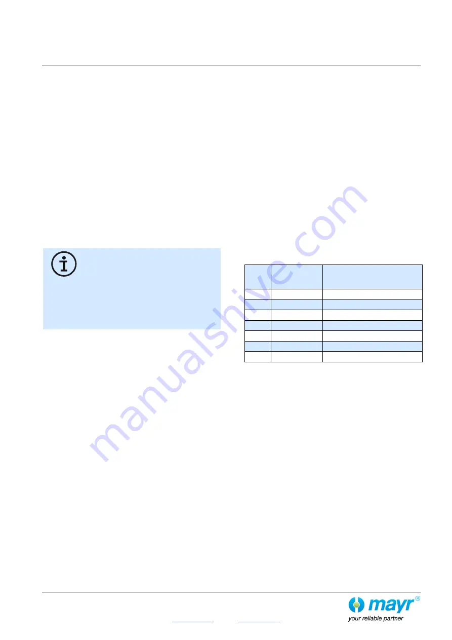
Table 2:
Size
Friction work
Q
a
[J]
Brake speed n
min
[rpm]
3
16
300
4
29
250
5
55
200
6
105
160
7
200
130
8
380
120
9
600
100


