background image


31


Here you can key in the number of the required programme and confirm your choice 

by pressing the ENT button.  

After  entering  the  programme  number,  the  field  selection  must  be  pressed  in 

order to activate the selected programme.  

By the pressing of key F1 you can return to the starting screen. 


If there is no programme saved under 

programme selection

, please press the option 

p

arameter entry 

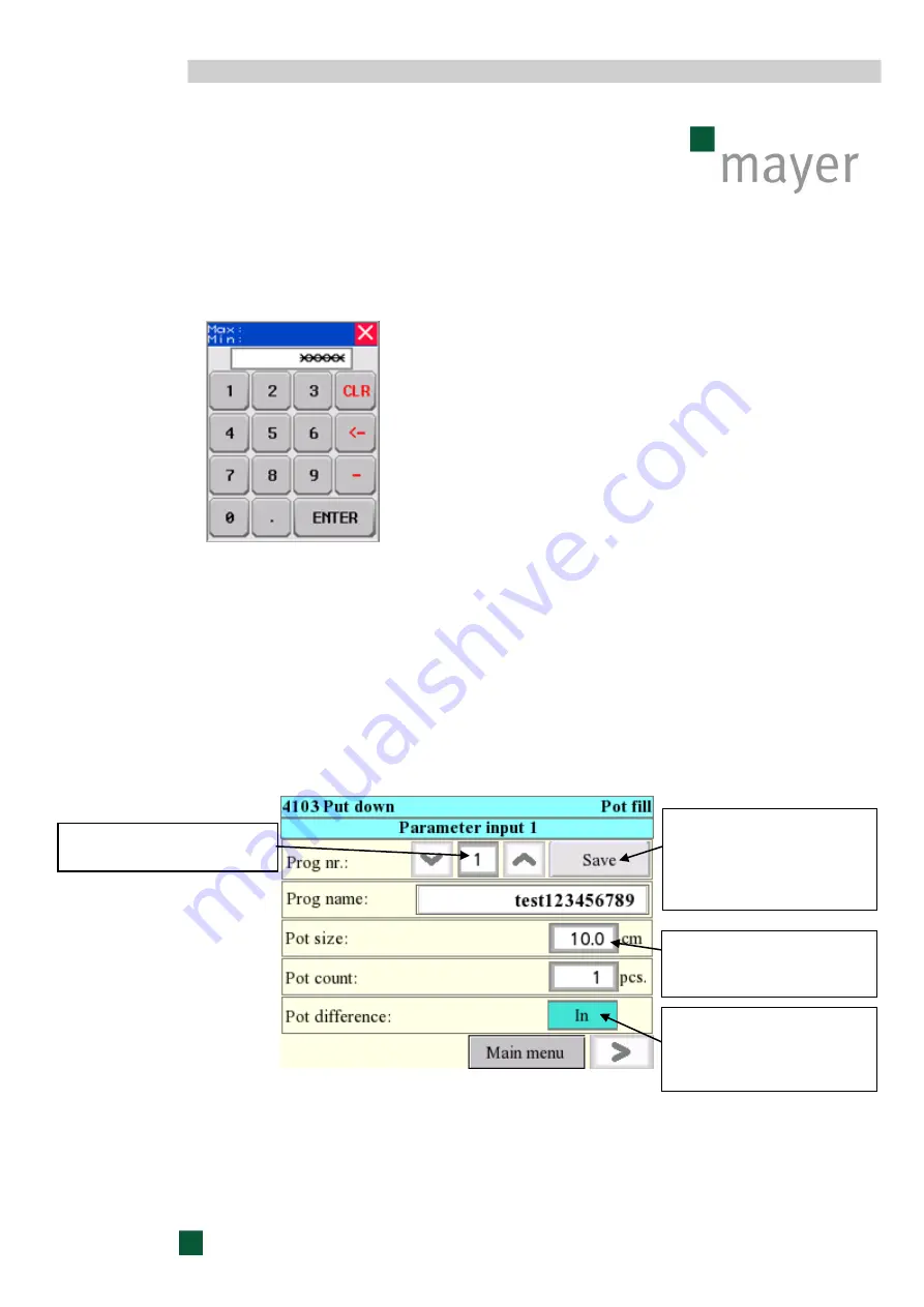
on the starting screen. This will open up an entry field where you can 

enter and save various parameters for the required machine programmes. 


After the individual entry fields are selected, the relevant keypads will appear with the 

help of which the required data can be entered. 


Number of programme to be 
created or modified 

New entries and 
modifications must always 
be saved, otherwise they 
will not be imported into the 
given programme. 

Only for information,  
shall not affect the 
programme. 

When p

ot difference

 is 

activated, one pot less will 
be placed in every second 
row. 

Содержание TR 4103

Страница 1: ...f Issue 01 02 2016 V1 0 Read carefully before installation commissioning and operation For further reference please keep this manual within easy reach of the equipment at all times Instruction manual Pot handling robot TR 4103 ...

Страница 2: ... 1 General information 2 Installation of the machine 3 Requirements for structural stability 4 Dismantling and disposal of the machine 5 Commissioning 1 Inspection prior to the initial commissioning 2 Initial start up of the machine 3 Stopping the machine 6 Operation 1 Standard operating procedures 2 Shutdown procedure 3 Measures before and after a prolonged standstill period 7 Machine malfunction...

Страница 3: ...s on mobile benches d Sorting potted plants With at least 3 interlinked POT HANDLING ROBOTS in operation The first POT ROBOT lifts the pots from the mobile bench and places them onto the conveyor belt While on the conveyor belt the pots are sorted and each sort is transported to a corresponding POT HANDLING ROBOT by means of conveyor belts Any utilization of the machine other than the intended use...

Страница 4: ...4 2 Structure Top view of POT HANDLING ROBOT TR 4103 rear right left front ...

Страница 5: ...he pot lifting unit swivels out Now the arm moves back into its starting position over the conveyor belt and waits until the accumulator is filled with pots again While the arm is swivelling back and inwards again the table is rolled forwards by the table feed by a previously set path length in order to secure enough space for the next row of pots to be placed on the table Once the accumulator is ...

Страница 6: ...6 Table Accumulator Pre accumulator Pot handling robot TR 4103 Conveyor belt Table feed Mayer pot handling robot ...

Страница 7: ...lator Accumulator Pre accumulator Pre accumulator Pot handling robot TR 4103 Pot handling robot TR 4103 Pots in alternating rows Pots in alternating rows Gaps between pots freely adjustable Gaps between pots freely adjustable Pots in parallel rows Pots in parallel rows ...

Страница 8: ...when working without alternation max 1740 mm Table width inner with alternation max 1640 mm alternation Table width inner without alternation max 1780 mm Additional parts Forks and accumulators to be selected according to pot size and gap between pots Hourly output rate see output chart Workplace related emission value 70dB A Output chart The output rates of MAYER POT HANDLING ROBOT TR 4103 are in...

Страница 9: ...r extra charge Pot forks Pot accumulator Blow off unit for cleaning the conveyor belt Table drive with query Attention When ordering spare parts and optional extras kindly remember to state the type and model number of your machine ...

Страница 10: ...fety related parts of control systems pl C Part 1 General principles for design Principles for risk assessment Interlocking devices associated with guards EMERGENCY SHUT OFF systems Electrical equipping of industrial machines Part 1 General requirements category 0 STO Safe torque off Safety of machinery Minimum gaps to avoid crushing of parts of the human body Safety of machinery Guards General re...

Страница 11: ...nctional condition with special regard to the protective guards and safety devices which must be checked on a regular basis and kept in a fully functional condition at all times the instruction manual is kept in a full and readable condition and within easy reach of the machine at its place of operation the equipment is used serviced and repaired by fully qualified and authorized operating personn...

Страница 12: ...ation to the safety signs and symbols ssed The safety signs and symbols together with the related warning texts are meant to call attention to the unavoidable residual risks associated with the use of the machine These residual risks may affect people the machine other objects and properties the environment In this instruction manual the following safety symbols are used This symbol suggests that ...

Страница 13: ...lowed at all times The personnel is to wear tight fitting work clothes at all workstations Wearing rings chains or bracelets is strictly prohibited For technological reasons the MAYER POT HANDLING ROBOT TR 4103 cannot be covered completely Nevertheless the protective shield fitted on the sides provide extra protection against the moving pot lifting unit It is strictly prohibited to reach behind th...

Страница 14: ...d All supply lines connected to the machine must be unimpaired Maintenance and repair work on the electrical equipment must be conducted by qualified and authorized electricians only Protective guards and safety devices are installed to protect the health and safety of the operating personnel and are under no circumstances to be changed removed or bypassed through altering the machine Residual cur...

Страница 15: ...pot handling robot marking the working areas and the prohibited areas a Automatic table feed Working area Prohibited area Table track Working area Working area Table track Table track Pot placing unit Pot placing unit Pot lifting unit ...

Страница 16: ...16 b Manual table feed Working area Prohibited area Table track Working area Working area Table track Table track Pot placing unit Pot placing unit Pot lifting unit Working area ...

Страница 17: ...pervision of an authorized person with sufficient experience The successful completion of an initiation training must be certified in a written format Control units are only to be operated by personnel properly and specifically trained for this purpose All employees conducting work on and around the machine must carefully read this instruction manual and sign a declaration stating that they have f...

Страница 18: ...hine is running it is strictly prohibited to loose screws of the safety guards and to remove the guards The guards may only be removed when servicing the machine At the guards the following warning decals are attached ...

Страница 19: ...than the hereinafter listed lifting tools and equipment be applied this can cause severe damage to the machine 1 Transportation While transporting the machine all due care must be paid to avoid it being damaged through any external force or due to careless loading and or unloading The consignment must be firmly fixed and secured during transportation as appropriate based on the method of transport...

Страница 20: ...n all current sensitive FI circuit breaker c Enough space must be secured for the assembly and installation work to be performed on the machine This requirement should be taken into account when arranging upstream and downstream machines d In order to make optimum use of the available machine capacity a continuous flow of pots and plants on the conveyor belts must be ensured Maximum operational ef...

Страница 21: ...use the fixture over the table tracks b Position the machine c Remove transport fixture d Arrange the machine aligning with the table track and at a height appropriate for the table base e Affix the table feed and the light sensor for table positioning 10B1 10B3 placing unit 10B4 10B5 lifting unit on the table track NOTE Please consider the total height of the machine when installing it ...

Страница 22: ...NG ROBOT TR 4103 at its place of operation for the first time the table feed must be attached to the table track of the table transport in a way that allows for the middle of the drive wheel on the electric motor to be in alignment with the row of pots previously placed there manually see schematic representation above ...

Страница 23: ...ble direction End of table switch 10B2 Start of table switch 10B1 Light sensor bracket Table Table track Table feed approx 20 30 cm Table full switch 10B3 Table direction Light sensor bracket Table Table track Table feed approx 20 30 cm Switch 10B4 Switch 10B5 ...

Страница 24: ... dimensions Length min 1 00 m Width min 1 00 m Depth min 0 20 m For the dowelling of the machine 4 screws with a minimum diameter of 10 mm and a minimum length of 120 mm should be used with each of the 2 legs 4 Dismantling and disposal of the machine Upon completing the full length of its operational life the machine must be disconnected from the power supply network and disposed of as specified b...

Страница 25: ...moved from the machine Check all electrical connections before starting the machine for the first time Activate all safety devices and Emergency OFF switches before starting up the machine Please consult the chapter on health and safety instructions as well 1 Inspection prior to the initial commissioning Prior to the initial commissioning of the machine kindly go through the following checklist Ar...

Страница 26: ... a For a smooth operation of the machine it is essential that the operating pressure be set properly The adjustment of pressure can be performed on the service unit The pressure must reach a minimum value of 5 bar and must not exceed a maximum value of 9 bar Should the operating pressure fall below the minimum of 5 bar the pressure control will be activated and the machine will stop ...

Страница 27: ...g the machine please complete the following procedure test running of the machine only to be performed in manual mode After switching on the machine the starting screen will be displayed on the control panel for 6 seconds ...

Страница 28: ...no table Red Error messages here you can read messages indicating machine error e g low pressure Settings Service technicians of the company Mayer can set machine functions through this option The machine can be operated as a single machine or interlinked in a configuration with various different functions Parameter settings Display of the selected operation in the given operational mode ...

Страница 29: ...nputs and outputs of the PLC control system are displayed here active inputs and outputs are marked yellow Manual operation mode The individual operations and functions of the machine can be activated by pressing the relevant buttons Automatic operation mode The individual operations and functions of the machine will be performed automatically First the required function must be set after the mach...

Страница 30: ...ere will be only two options to choose from By pressing key F1 you can return to the starting screen Next you need to select the required programme Upon pressing the option programme selection on the starting screen the following screen will be displayed Through activating the fields or you can select the required programme which will appear in the Number Field Then if you press the number field a...

Страница 31: ...meter entry on the starting screen This will open up an entry field where you can enter and save various parameters for the required machine programmes After the individual entry fields are selected the relevant keypads will appear with the help of which the required data can be entered Number of programme to be created or modified New entries and modifications must always be saved otherwise they ...

Страница 32: ...ter the number of pot rows to be placed on the table depending on the table length Attention There is no correlation between the pot size and the length of the table as a result of which the track length must always be checked for the selected number of rows Should a number be entered for the number of rows the track length will be calculated automatically and the result will appear in the field r...

Страница 33: ...y for each fork pot size Table position This represents the distance between the table position activating reflective light sensor 10B1 and the position of the first row of pots on the table Parameter entry field 3 will only appear on the display if the function feed is pre set among the basic entries of the machine Feed The pots will be placed on the table then the table feed moves back to a pred...

Страница 34: ...nveyor belt off Here you can set the time at which with the pot barrier closed the conveyor belt and the pot handling robot will be stopped By activating key F3 you can always return to the previous screen By activating key F4 you can always move on to the next screen By activating key F1 you can always return to the starting screen Parameter entries for the pot lifting unit ...

Страница 35: ...tangled Lifting This refers to the time interval during which the arm moves back to the conveyor belt pots are lifted from the table before the table rolls back Alternating rows see Pot placing Table feed OFF With this option you can set whether the table feed should be stopped immediately after the pots are in the fork or only after the time interval set through the field stopping time for table ...

Страница 36: ... time interval that runs out when light sensor 12B5 cannot detect any more pots on the conveyor belt When the pre set time runs up the transport arm moves back to the conveyor belt and places the pots down there Once all pre settings have been finalized the machine can be started in the manual mode by activating the field manual operation mode Then the following screen will be displayed The select...

Страница 37: ...be switched to continuous forward running mode Continuous operation table In stop operation the table drive can be switched to continuous backward running mode Start Through this option you can start the manual operation mode Operations can only be performed after the manual operation mode is started and the given operation is enabled via the relevant safety prompts The manual operation mode can o...

Страница 38: ...per has moved back Should there be no irregularities e g unusual noises or error messages found during the trial run the machine can be switched into automatic operation mode The automatic mode can be started by activating the field automatic operation mode in the starting screen Consequently the following screen will appear Screen for the placing unit Display of selected number of pot rows Number...

Страница 39: ... modified programme is activated again Delete Through this option you can delete the number of placed pots Manual operation mode When the automatic mode is stopped you can switch to manual operation mode directly through this option PLC in out Through this option you can retrieve all inputs and outputs of the PLC control system Error messages Error messages will be displayed here continuous operat...

Страница 40: ... cylinder retracted Alternating rows extended If you select the option alternating rows extended the first row of pots on the table will be removed with the cylinder extended In AUTOMATIC OPERATION MODE the robot performs its operations according to the pre set parameters The machine can be stopped by activating the internal or external STOP buttons Whenever an error message is generated the machi...

Страница 41: ... and OUT BACKWARDS I With the gripper swivelled out the arm can always be moved II With the placing unit Arm forwards can be used in all cases Arm back can only be used if the gripper is swivelled out III With the lifting unit Arm forwards can be used in all cases Arm back can only be used if the belt is clear and the machine is running in AUTOMATIC OPERATION MODE ...

Страница 42: ... the help of the buttons IN FORWARDS and OUT BACKWARDS After pressing the option selection the control image CONVEYOR BELT will appear on the screen for the placing unit and the lifting unit The belt can be started by activating the IN FORWARDS button After pressing the option selection the control image ALTERNATION will appear Alternation can be controlled by means of the buttons IN FORWARDS and ...

Страница 43: ...ary case the machine will be stopped by activating the STOP button on the control panel or by activating the flexible START STOP switch b In the event of emergency the machine can be stopped by activating the Emergency OFF button Note Please consult section 6 2 on the shutdown procedure as well ...

Страница 44: ...lear Drive 1 2M1 Drive 2 2M1 Valves 14Y1 Pot barrier 14Y5 Alternator 14Y6 Fork on demand 10S1 Pressure 11B8 Gripper 1 swivelled in 11B6 Gripper 1 swivelled out 12B1 Gripper 2 swivelled in 11B7 Gripper 2 swivelled out 10B8 Arm Pos Conveyor 11B1 Creep feed Conveyor 11B3 Creep feed Table 11B2 Arm Pos Table 14Y2 Gripper 1 14Y3 Gripper 2 14Y3 Gripper slow mo only without additional fork pivoting START ...

Страница 45: ...ned at both ends You must determine the distance between the first pot row and the table edge at the starting end of the table and the distance between the last pot row and the table edge at the end of the table What would be the optimum setting for the table feed The table feed should be adjusted to the required gap between the pot rows b Changing the forks and accumulators The MAYER POT HANDLING...

Страница 46: ...inally the clamping levers must be tightened closely on order to firmly fix the fork in its position The electric plug of the switch control must then be connected to the network again only on the lifting unit c Basic settings of the MAYER POT HANDLING ROBOT TR 4103 Automatic and manual operation mode In order to secure a smooth operation of the machine you must make sure that the operational pres...

Страница 47: ...s case the gripper stands still over the conveyor belt The empty table will now be rolled on until the switch table in position 10B1 is passed The POT HANDLING ROBOT automatically starts to place the pots again onto the empty table If the position switches for the table are clear 10B1 10B2 10B3 the table feed will remain inactive Should the table pass light sensor 10B2 the table feed will start to...

Страница 48: ...swivels in Proximity switches 11B8 and 12B1 signal gripper swivelled in and they put the arm into operation The arm controlled through frequency converter 4A1 goes over the acceleration ramp to its maximum speed moving towards the table After it has passed proximity switch 11B3 the speed will be reduced and the arm moves slowly into its end position 11B2 Once proximity switch 11B2 signals position...

Страница 49: ...w close enough to the table edge to secure an optimum utilization of the available surface Placing pots in alternating rows The process is performed in the same way as described in the case of pot placement in parallel rows with the difference that the alternator is activated with every second row After the second pot row has rolled into the accumulator the gripper swings in and the arm moves forw...

Страница 50: ...s in order to disentangle the plants feed backwards distance to be set in advance in the programme via the option disentangle Once the required disentangling distance has been covered and light sensor 12B5 signals belt clear the arm will return to the conveyor belt After proximity switch 11B1 is passed the conveyor belt stops As soon as the arm reaches its position over the conveyor belt switch 10...

Страница 51: ...orth in chapter 7 2 of this manual must be strictly observed h Manual operation mode Placing of pots lifting of pots Preliminary settings must be completed as described in the sections on the automatic operation mode Programme selection On the starting screen the option MANUAL OPERATION MODE must be selected MANUAL ALTERNATING ROWS or MANUAL PARALLEL ROWS on the display Starting the Manual operati...

Страница 52: ...amme will automatically continue the operation from the point where it has been interrupted b In the event of emergency the machine can be stopped by activating the Emergency OFF button Once the Emergency OFF button is activated the machine will shut down immediately After unlocking the Emergency OFF button the machine must be switched into manual operation mode and the interrupted operation must ...

Страница 53: ... schedule The machine must be protected covered against eventual contamination and moisture The machine must be disconnected from its supply networks electrical network and compressed air supply b After a prolonged standstill period The machine must be checked by means of visual inspection The machine must be connected to the power network The machine can be started as described in the chapter on ...

Страница 54: ... or property damage In unsecured manual operation mode the risk of injury due to the crushing or squeezing of body parts is considerably increased 1 Malfunction procedures Should any malfunction occur during the operation of the machine please follow the procedure set forth below 1 Stop the machine immediately by pressing the STOP button or by activating the Emergency OFF button as required by the...

Страница 55: ...inder stop settings The alternating cylinder strikes to intensively in the end position The throttle check valve is not set properly Correct throttle check valve settings Alternating rows are not managed well during pot lifting No compressed air available Defective valve Defective cylinder Check air pressure Replace valve or cylinder Table will not roll through Incorrectly set table dimensions tab...

Страница 56: ...ated A motor protection switch on the drives is activated e g table drive conveyor belt Motor consumes too much power or gets overheated Check motor to establish if the voltages are OK or if there is a mechanical problem Problem with the frequency converter The frequency converter has switched off The rated motor current of the motor running through the frequency converter has been exceeded Check ...

Страница 57: ...rol software of the machine must exclusively be performed by MAYER GmbH Co KG All fuels lubricants and auxiliary materials that are not re used must be disposed off in line with the relevant environmental safety regulations Please consult the chapter on health and safety instructions as well Maintenance and servicing of the machine is associated with the following specific types of hazards Buildin...

Страница 58: ...machine Through the use of original MAYER components this requirement is automatically fulfilled 2 Maintenance schedule The maintenance demand of the machine has been reduced to a minimum through the application of maintenance free machine elements The following parts must be lubricated with standard lubricating grease at the time intervals set forth in the following chart Description Interval Cha...

Страница 59: ... Grease guides every week The oil filling in the drives of the conveyor belt the placing unit and the table feed shall be exchanged after ca 10 000 service hours Recommended Oil Types BP Energol SG XP 460 KLÜBER Syntheso D 460 EP MOBIL Glygole 80 SHELL Tivela SD Or other synthetic oils VG 460 with a viscosity of 440 500 cST at 40 degrees Celsius ...

Страница 60: ...60 9 List of spare parts ...

Страница 61: ...mmer Part number Stück Amount 1 Kettenrad oben 4100 02 02 01 00 1 Chain wheel above 2 Kettenrad unten 4100 02 02 02 00 1 Chain wheel below 3 Rollenkette 111136 1 Chain belt 4 Verschlussglied 111143 2 Chain lock 5 Flanschlager 4100 02 02 04 00 2 Flange bearing Kettenantrieb links Chain drive to left Pos Benennung Description Artikelnummer Part number Stück Amount 1 Kettenrad oben 4100 02 02 01 00 1...

Страница 62: ... 00 2 Flange bearing 2 Laufschiene 4100 04 01 04 00 4 Rail 3 Führungsrolle 4100 04 01 05 03 8 Guide roller 4 Buchse 4100 04 01 05 04 4 Bush 5 Exzenterbuchse 4100 04 01 05 05 4 Eccentric bush 6 Schrägkugellager 111320 8 Angular ball bearing Schwenkantrieb Swing drive Pos Benennung Description Artikelnummer Part number Stück Amount 1 Kettenrad 4100 04 02 01 02 1 Chain wheel 2 Kettenrad 4100 04 02 02...

Страница 63: ...heck valve 3 Flexo Kupplung 111207 1 Flexo coupling Schwenkantrieb Swivel drive Pos Benennung Description Artikelnummer Part number Stück Amount 1 Druckluftzylinder 111208 1 Compressed air cylinder 2 Drosselrückschlagventil 111212 2 Throttle check valve 3 Näherungsschalter 111213 2 Proximity switch Sammler Collector Pos Benennung Description Artikelnummer Part number Stück Amount 1 Druckluftzylind...

Страница 64: ...ressure checker 5 Druckregler 111185 1 Pressure controller 6 Manometer 111186 1 Manometer 7 Drosselrückschlagventil 111193 1 Throttle check valve 2 Electrical spare parts Hauptantrieb Main drive Pos Benennung Description Artikelnummer Part number Stück Amount 1 Elektromotor 4100 02 01 01 00 1 Electric motor Tischvorschub Table feed Pos Benennung Description Artikelnummer Part number Stück Amount 1...

Страница 65: ...kereinsatz 102111 1 Connecting part Aufnehmgabel Pick up fork Pos Benennung Description Artikelnummer Part number Stück Amount 1 Mikroschalter 109963 2 2 Snap switch Schutzhaube Protecting cap 102085 2 Nur am Aufnehmer Only at pick up Pos Benennung Description Artikelnummer Part number Stück Amount 1 Reflexlichtschranke 114640 1 Reflected light equipment 2 3 Kabel Cable Reflektor 114938 103863 1 1...

Страница 66: ...66 10 Pneumatic and electrical diagrams ...

Страница 67: ...67 Pot collector Staggered order Swivel drive ...

Страница 68: ...68 Pot collector staggered order Swivel drive additional swivelling ...

Страница 69: ... for warranty but not manufactured by our company e g engines are only warranted by us for the time period and to the extent covered by the warranty offered to us by our supplier Eventual replaced parts remain our property This warranty shall not apply if the defect in question is due to the purchaser s improper care or use of the product and or excessive use or handling or in the event if the mac...

Страница 70: ...he guarantee period under the restriction that no considerable changes shall be made to the product sold the product quality or its value shall not be reduced in any way and the changes and modifications shall be acceptable to the purchaser Thank you for your decision to purchase this state of the art product We wish your company every success in the future If our products and services have been t...

Отзывы: