


7
current values at 400V in Section 1.3 and make sure
to recalculate it for the voltage used on board. Start
current may be limited to about half the above
amount by using a "Star-Delta" starter. However,
start torque is thereby limited to loads of about 25-
30% of the windlass rated capacity.
“Star-Delta” and “soft starters” are not recommended
for starting windlass motors, as the motor torque is
severely limited during start up period. Since these
motors often have to start under load (when
retrieving the ground tackle), they might not be able
to move until they reach the full voltage and torque.
The benefit of starting at lower current would
therefore be lost. Also, the motor brake would
release immediately on start-up, which could cause
short movement of the chain in opposite direction.
The Variable Frequency Drives (VFD) offer accurate
control of current during start up period while
keeping high motor torque. They also offer various
other benefits like:
infinite speed control
running the windlass over its nominal speed
accurate current overload and thermal overload
2.7
POWER CONECTIONS TO AC MOTOR
Remove the motor terminal box cover and take care
not to misplace the sealing gasket and screws.
Select a suitably sized, waterproof cable gland for
the armoured supply cable. The selected gland fitting
must fit the terminal box, be capable of anchoring the
armoured cable, and allow an effective waterproof
entry seal to be made.
Make the line connections to motor terminals as per
motor nameplate or motor card. Fit link plates
correctly, if required. Make also an effective earth
connection.
Separately and similarly, enter the 2 thermistor
cables to the motor terminal box, and connect to the
two auxiliary terminal connectors of the thermistor
circuit (see wiring diagram in Appendix C).
Our AC motors are equipped with a disc brake to
stop back winding when the windlass stops under
load. The brake should be wired as follows:
‘Direct on Line’ start, single speed motor
On single speed motors, the brake rectifier is already
connected to motor terminal block and no additional
wiring is required.
‘Direct on Line’ start, dual speed motor
In case of using a two-speed, pole changing motor, a
separate power supply for the brake is required.
Remove the existing connection from motor
terminals to the brake rectifier and bring in brake
power supply from contactor in the starter unit (see
wiring diagram of DOL starter in Appendix C).
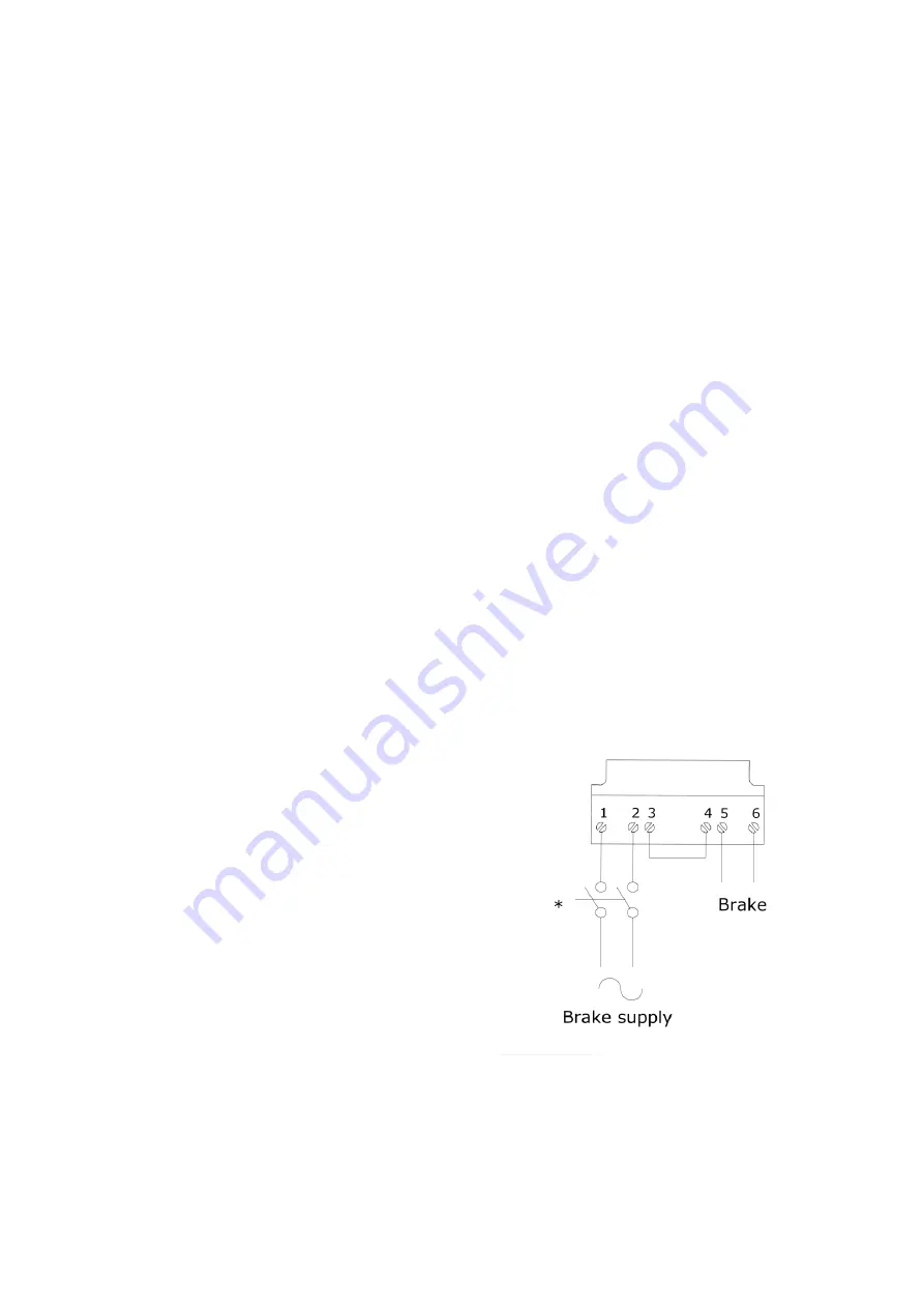
VFD controller
If the VFD, controller is used, the brake also needs a
separate power supply from the VFD unit to ensure
appropriate timing of engaging and disengaging the
*Brake supply contactor should work in parallel
With motor supply contactor. The contacts
Should be suitable to open very inductive
loads
Picture 2.5
Brake Connections
Содержание CAPSTAN 8000 Series
Страница 1: ...CAPSTAN 8000 SERIES...
Страница 15: ...13 APPENDIX A Dimensional Drawings...
Страница 16: ...14...
Страница 17: ...15...
Страница 21: ...19 APPENDIX C Installation Schematics...
Страница 22: ...20...
Страница 23: ...21...
Страница 24: ...22...
Страница 27: ...25...