background image

INSTALLATION

4 – 18

4

Mounting Drive in System

Turn the computer OFF, disconnect the power cord and remove the cover. Refer to the computer user’s manual for information on removing the cover.

Each system manufacturer uses different types of cases, including desktop, mini-tower, full tower and other special configurations. As a result, there are many
different possible mounting locations that could be used.

In a typical system case, there are specific 3.5 inch and 5.25 inch bays available for storage devices. When a 3.5 inch mounting bay is available, mounting
brackets and rails are not required.  If a 5.25 inch mounting bay is used, mounting brackets (and possibly rails) will be required to mount the Maxtor hard drive
in the system case. Refer to the system manufacturers user’s manual or contact the system manufacturer directly for additional information.

NOTE:

Some computer manufacturers have system cases that require custom mounting brackets and/or rails to physically mount a hard drive. If the ANSI-

standard brackets and rails provided in the Maxtor Hard Drive Kit cannot be used in your system case, you will need to obtain custom brackets and rails from
your system manufacturer.

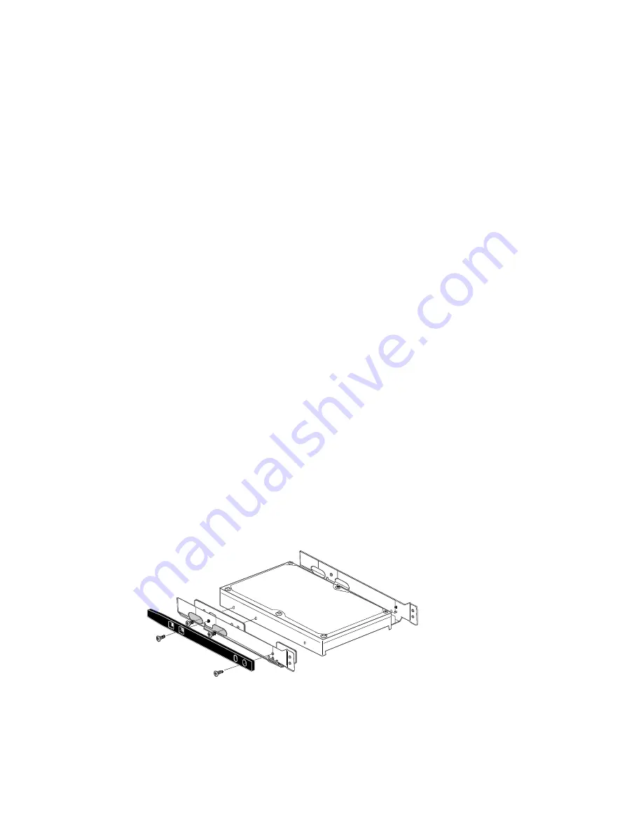
Installing 5.25-inch Mounting Brackets and Rails

If the Maxtor hard drive is being mounted in a 5.25 inch drive bay, the following figure shows how to attach the brackets and/or rails to the drive. If the drive is
being installed in a 3.5 inch bay which requires the use of rails, they may be installed directly on the drive without brackets.

Systems Using Cable Select

IMPORTANT

 – Most systems do not use this feature. Unless you are sure that your computer system supports Cable Select, do not set up the drive with this

feature enabled.

Maxtor hard drives support Cable Select. The Cable Select method of drive identification allows the system to identify Master and Slave IDE devices based
upon the position (connector) the IDE device is attached to on the interface (ribbon) cable.

A special IDE cable select interface (ribbon) cable is 

required

 for systems using the Cable Select feature.

The ribbon cable included in Maxtor kits is a standard IDE cable and cannot be used in systems that use Cable Select. Systems that use Cable Select do not
support the standard Master/Slave definitions described above and the standard IDE interface (ribbon) cable 

cannot 

be used on these systems.

If your system supports this feature, refer to the system user’s manual or contact the system manufacturer for specific procedures for installing hard drives. On
Maxtor DiamondMax 2880 hard drives, Cable Select is enabled by installing a jumper on J48.

Relationship to Other IDE Devices

IDE devices such as a CD-ROM or tape drive also have the jumper definitions for Master and Slave. The difference between a hard drive and these devices is
that they require special software drivers in order to communicate properly with the system. Hard drives do not require additional drivers to communicate with
the system. Because of limitations in the software drivers provided with CD-ROMs, tape drives and other IDE devices, Maxtor does 

NOT

 recommend that a

hard drive be a slave to a CD-ROM or other IDE devices only to another hard drive. The software drivers for non hard drive IDE devices do not provide
adequate support for communications to a hard drive as a slave device. Maxtor recommends that hard drives be the master to any other IDE devices except
another hard drive.

Installing in Drive Bay

After the hard drive is prepared with mounting brackets/rails, if required, and the jumpers are set correctly, the drive can be mounted in a drive bay and
secured. 

Note: 

The computer system the Maxtor hard drive is being installed in may use standard or a unique mounting and placement method. Refer to the

computer user’s manual or contact the system manufacturer for detailed mounting instructions for that specific system.

Содержание 90256D2

Страница 1: ...All rights reserved Printed in the U S A 2 98 Corporate Headquarters 510 Cottonwood Drive Milpitas California 95035 Tel 408 432 1700 Fax 408 432 4510 Research and Development Engineering Center 2190...

Страница 2: ...Revisions Manual No 1390 V E R O N C E N O I T C E S N O I T P I R C S E D E T A D A B 2 9 8 8 7 l l A l a i t i n I e s a e l e r 3 0 1 8 9...

Страница 3: ...to product failure damage and invalidation of all warranties 1 BEFOREunpackingorhandlingadrive takeallproperelectro staticdischarge ESD precautions includingpersonnelandequipmentgrounding Stand alone...

Страница 4: ...urately and in the form you prefer a fax a downloaded file or a conversation with a representative Manual Organization This hard disk drive reference manual is organized in the following method Sectio...

Страница 5: ...re shown in all uppercase type All signals are either high active or low active signals A dash character at the end of a signal name indicates that the signal is low active A low active signal is true...

Страница 6: ...imes make these performance series disk drives especially well suited to high speed desktop and server applications DiamondMax 2880 Key Features ANSI ATA 4 compliant PIO Mode 4 interface Enhanced IDE...

Страница 7: ...improves overall AT interface performance by significantly improving burst and sustained data throughput Multi word DMA EISA Type B Mode 2 Supports multi word Direct Memory Access DMA EISA Type B mode...

Страница 8: ...ctor values The physical address is then used to access or store the data on the disk and for other drive related operations Defect Management Zone DMZ Each drive model has a fixed number of spare sec...

Страница 9: ...fer begins immediately Automatic Write Reallocation AWR This feature is part of the write cache and reduces the risk of data loss during deferred write operations If a disk error occurs during the dis...

Страница 10: ...s up to eight head selection depending on the model read pre amplification and write drive circuitry Read Write Heads and Media Low mass low force magneto resistive read write heads record data on 3 5...

Страница 11: ...Drive Support Two drives may be accessed via a common interface cable using the same range of I O addresses The drives are jumpered as device 0 or 1 Master Slave and are selected by the drive select...

Страница 12: ...5 0 0 0 0 0 0 5 L E D O M 8 D 2 5 1 1 9 7 D 8 0 0 1 9 6 D 4 6 8 0 9 6 D 0 4 8 0 9 5 D 0 2 7 0 9 5 D 0 4 6 0 9 4 D 6 7 5 0 9 4 D 5 2 5 0 9 3 D 2 3 4 0 9 2 D 8 8 2 0 9 2 D 6 5 2 0 9 s e m i T k e e S l...

Страница 13: ...imensions R E T E M A R A P D R A D N A T S C I R T E M t h g i e H h c n i 2 0 1 s r e t e m i l l i m 9 5 2 h t g n e L s e h c n i 7 7 5 s r e t e m i l l i m 6 6 4 1 h t d i W s e h c n i 2 0 4 s...

Страница 14: ...E G A R O T S G N I T A R E P O N O N e r u t a r e p m e T C 5 5 o t C 5 3 2 0 5 d o h t e m E 0 1 8 D T S L I M r e p C 0 4 e r u t a r e p m e t w o l 3 1 0 5 d o h t e m E 0 1 8 D T S L I M r e p...

Страница 15: ...ility 1 per 1014 bits read Data errors non recoverable Average data error rate allowed with all error recovery features activated Component Design Life 5 years minimum Component design life is defined...

Страница 16: ...guration Radiated Electromagnetic Field Immunity IEC 801 3 Class 2 compliance Radiated Magnetic Field Immunity Per MIL STD 461 462 Method RD01 15 Hz to 100 kHz stand alone test configuration Standard...

Страница 17: ...R connect a live connector to the hard drive s IDE interface connector Electro Static Discharge ESD To avoid some of the problems associated with ESD Maxtor advises that anyone handling a disk drive u...

Страница 18: ...f damage in transit Notify the carrier immediately in case of damage to the shipping container As they are removed inspect drives for evidence of shipping damage or loose hardware If a drive is damage...

Страница 19: ...tatic bag Physical Installation Recommended Mounting Configuration The DiamondMax 2880 drive design allows greater shock tolerance than that afforded by larger heavier drives The drive may be mounted...

Страница 20: ...g Data Have you backed up your hard disk Periodic backup of important data is always a good idea Whenever your computer is on there is the potential for losing data on your hard drive This is especial...

Страница 21: ...y of a drive larger than 8 4 GB either a BIOS upgrade a BIOS enhancer card or the MaxBlast software version 9 06M or newer will be required to correctly support the drive Ultra Direct Memory Access UD...

Страница 22: ...ationship to other IDE devices attached to the same cable Primary Master Slave Definitions Some hard drive manufacturers use three definitions Primary Master and Slave The manufacturers which use the...

Страница 23: ...Master and Slave IDE devices based upon the position connector the IDE device is attached to on the interface ribbon cable A special IDE cable select interface ribbon cable is required for systems us...

Страница 24: ...Attach an available IDE interface connector to J1 on the Maxtor hard drive The connector on the cable provided with the Maxtor Hard Drive Kit is keyed and will only fit in one orientation Do not force...

Страница 25: ...f the other BIOS settings or other parts of the system may not work correctly BIOS CMOS Parameters In order for the computer system to recognize the new Maxtor hard drive it is necessary to set the sy...

Страница 26: ...and Sector values with the values listed on the drive label The drive label is located on the top cover of the drive The fields LZone Landing Zone and WPcom Write Pre comp are not used by the Maxtor...

Страница 27: ...the system manufacturers user s manual the operating system user s manual or contact the manufacturer directly B Preparing the hard drive using MaxBlast installation software 1 Boot the system with t...

Страница 28: ...TO DETECT follow the instructions in Section 7 to prepare the hard drive using the MaxBlast installation software If other BIOS settings were used access the system BIOS SETUP program and set the BIOS...

Отзывы: