Range Test
Once the Ethernet RF Modem has been setup for com port communications, a
wireless link between devices can be created for the transportation of data.
Hardware Setup
Using the components listed on page one of this quick start guide, assemble the
hardware needed for the range test.
1. Connect a PKG-E (Ethernet) RF Modem and a PC to active Ethernet ports of the
same local network using standard CAT5 cables [Figure 2].
2. Attach serial loopback adapter to the DB-9 serial connector of the PKG-R
(RS-232) RF Modem. The adapter configures the PKG-R RF Modem to function
as a repeater by looping serial data back into the modem for retransmission.
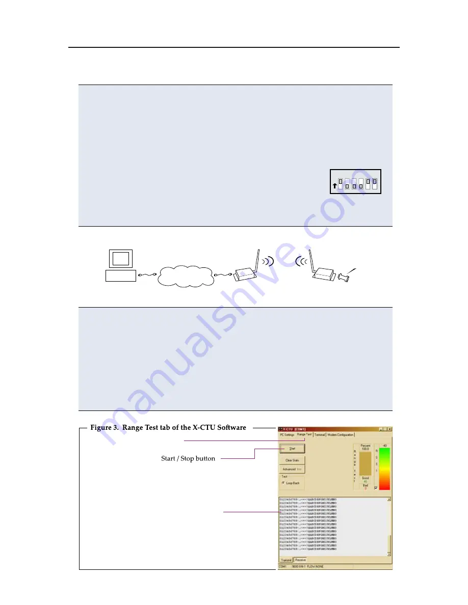
3. Configure the PKG-R RF Modem for RS-232 operation
using the built-in DIP Switch. Switches 1, 5 & 6 are ON (up)
and the remaining switches are OFF (down).
4. Attach RPSMA antennas to both RF Modems.
5. Power both RF Modems with power supplies (included w/ accessory packages).
Figure 2. Hardware Setup for Range Test
Run Range Test
1. Select the “PC Settings” tab; then highlight the com port [Figure 1 - ‘Com Port
Setup’ section] that was setup in the ‘Ethernet RF Modem Discovery’ section.
2. Select the baud rate from the ‘Baud’ dropdown list that matches the interface
data rate of the modem (BD parameter = 3 (9600 baud) by default).
[Figure 1 - ‘Com Port Setup’ section]
3. Select the “Range Test” tab [Figure 3]; then select the ‘Start’ button to begin
range test.
4. Move the remote PKG-R (RS-232) away from the PKG-E (Ethernet)
and observe packet information to determine the range of the wireless link.
Range Test tab
Packet Information
Local Ethernet
(TCP/IP) Network
PC
PKG-E (Ethernet)
PKG-R (RS-232)
(w/ loopback adapter)
O
N
1 2 3 4 5 6


