Evaluates: MAX7349/Emulates: MAX7347/MAX7348
MAX7349 Evaluation Kit
______________________________________________________________________________________
13
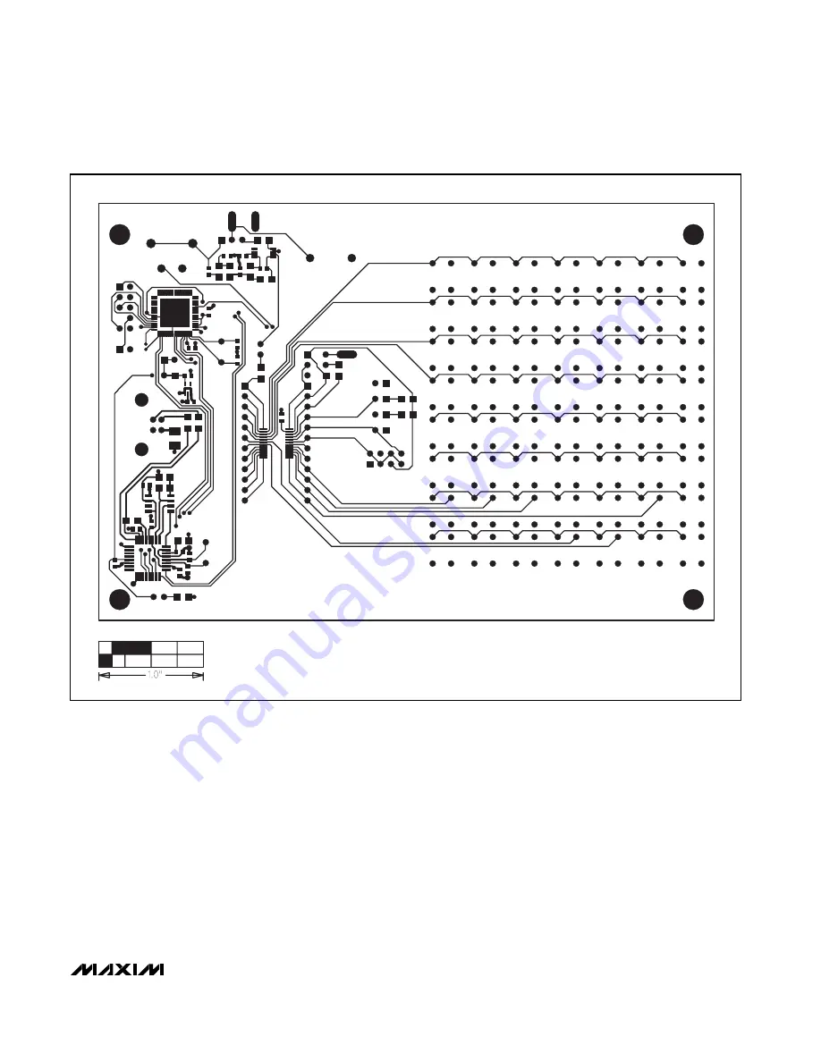
Figure 4. MAX7349 EV Kit PC Board Layout—Component Side
Страница 1: ...333KA C6 C7 2 22pF C0G ceramic capacitors 0603 TDK C1608C0G1H220J Murata GRM1885C1H220J C8 C9 2 10pF C0G ceramic capacitors 0603 Murata GRM1885C1H100J TDK C1608C0G1H100J C18 C19 2 1 F 6 3V min X7R cer...
Страница 2: ...allation Windows XP shows a warning message indicating that the MAX7349 Evaluation Kit 2 _______________________________________________________________________________________ DESIGNATION QTY DESCRIP...
Страница 3: ...x7E Pins 5 and 6 AD0 VDD I2C address 0x74 0x76 JU1 Pins 7 and 8 AD0 SDA I2C address 0x78 0x7A Pins 1 and 2 Pizeo Sounder P1 driven directly by SOUNDER output JU2 Pins 2 and 3 Pizeo Sounder P1 driven t...
Страница 4: ...takes when INT is active History Window Each register read or write event is recorded in a scrol lable text window underneath the interrupt handler actions Keyboard Navigation When you type on the PC...
Страница 5: ...h ROW0 the MAX7348 can be emu lated by using a subset of the MAX7349 pins and regis ter bits See Tables 2 and 3 Emulating the MAX7347 The MAX7347 behaves just like the MAX7349 except it has fewer colu...
Страница 6: ...RT7 2 ROW0 1 ROW0 1 ROW0 3 ROW1 2 ROW1 2 ROW1 4 ROW2 3 ROW2 3 ROW2 5 ROW3 4 ROW3 4 ROW3 6 COL3 PORT3 5 COL3 PORT3 7 COL4 PORT4 6 COL4 PORT4 8 ROW4 7 ROW4 5 ROW4 9 ROW5 8 ROW5 6 ROW5 10 ROW6 9 ROW6 7 R...
Страница 7: ...R W 0 FIFO 0111 xx0 R W 1 Debounce Port Enable No COL7 PORT7 No COL6 PORT6 No COL5 PORT5 No COL7 PORT7 No COL6 PORT6 No COL5 PORT5 No COL4 PORT4 No COL3 PORT3 0111 xx0 R W 2 Auto Repeat 0111 xx0 R W...
Страница 8: ...H1 12 U1 MAX7349 1 2 3 VDD JU3 VDD C1 0 1 F VDD VDD R9 470 LED2 RED COL7 PORT7 1 2 3 VDD JU6 INTVDD INT R15 10k JU1 5 JU1 6 JU1 8 JU1 7 JU1 3 JU1 1 JU1 HEADER 2 x 4 JU1 4 JU1 2 SCL AD0 SDA VDD VDD SO...
Страница 9: ...2 1 KEY40 ROW0 COL4 PORT4 KEY39 2 1 ROW7 2 1 KEY38 ROW6 2 1 KEY37 ROW5 2 1 KEY36 ROW4 2 1 KEY35 ROW3 2 1 KEY34 ROW2 2 1 KEY33 ROW1 2 1 KEY32 ROW0 COL3 PORT3 KEY31 2 1 ROW7 2 1 KEY30 ROW6 2 1 KEY29 RO...
Страница 10: ...12 43 P5 7 MISO 41 P5 6 SCLK 40 P5 5 MOSI 39 SP5 4 SS 38 P5 3 TX1 INT11 37 P5 2 RX1 INT10 36 2 5V VDDIO EXPOSED PADDLE CONNECTS TO GND 35 32KIN 34 32KOUT Y3 32 768kHz C24 0 1 F VDDIO C23 0 1 F 2 5V SD...
Страница 11: ...AVVC 26 13 Y2 6MHz C6 22pF C7 22pF VDDIO RTS CTS DTR DSR DCD TXLED RSTOUT RESET RXLED 15 10 PWRCTL PWREN SLEEP RI C15 0 1 F C12 0 1 F C14 0 1 F C13 0 1 F R7 470 R12 27 R13 27 C5 0 033 F R2 15k P2 3 P2...
Страница 12: ...MAX7349 Emulates MAX7347 MAX7348 MAX7349 Evaluation Kit 12 ______________________________________________________________________________________ Figure 3 MAX7349 EV Kit Component Placement Guide Comp...
Страница 13: ...ates MAX7349 Emulates MAX7347 MAX7348 MAX7349 Evaluation Kit ______________________________________________________________________________________ 13 Figure 4 MAX7349 EV Kit PC Board Layout Component...
Страница 14: ...the circuitry and specifications without notice at any time 14 ____________________Maxim Integrated Products 120 San Gabriel Drive Sunnyvale CA 94086 408 737 7600 2006 Maxim Integrated Products Printe...