


Copyright Maxford USA 2017
Page 6 of 12
S171201
After-sales service and return policy and instructions:
1.
Inspect your order upon delivery for any missing, damaged or unsatisfactory part(s). If you believe
there is a problem, you must call us at 562-529-3988 (Monday through Friday except holidays,
between the hours of 9 AM and 5 PM Pacific time) before you begin assembly and within 10 days from
receipt of your purchase. During this telephone conversation, and with your support, we will
determine how to resolve your concern.
2.
To request a return-merchandise authorization number (RMA#), call 562-529-3988 (Monday through
Friday except holidays, between the hours of 9 AM and 5 PM Pacific Time). If we elect to issue you an
RMA#, you must clearly mark this RMA# on the outside of the package. (No return or exchange will be
authorized after 10 days from the date of your receipt of the product; any package delivered to us
without a Maxford USA RMA# is subject to being returned to the sender, as received, with return
postage payable upon delivery.) Returned merchandise must be in its original condition as received
from Maxford USA, with no assembly or modification, in the product’s original packing materials,
complete with any included printed materials, manuals and accessories. Return shipping and
insurance charges must be prepaid by you, the buyer.
3.
Returned merchandise that is accepted by Maxford USA for credit is subject to a 10% to 20%
restocking fee (the final amount will be determined by Maxford USA upon receipt and examination of
the returned merchandise).
Return address:
Maxford USA
15939 Illinois Avenue, #B-C
Paramount, CA 90723
I
MPORTANT
: Print the RMA# issued by Maxford USA
on your package
near our address.
VIII. PHOTO INSTRUCTIONS AND ASSEMBLY NOTES
If you use glow engines
, use the following instructions to install both engines:
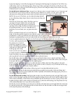
Secure the servo-type connector of a throttle-servo extension to this
end of the string preinstalled in the wing panels.
NOTE: if using an optional onboard glow-plug driver, also secure its
wires to this string.
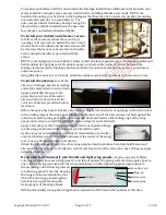
Use the string to pull the wires from the opening in the top of the wing
toward the root rib, then guide the wire(s) down and out through the
oval-shaped opening pictured below.
NOTE: if Mylar covers
any needed opening,
use a sharp hobby knife
to cut and remove the
Mylar near that
opening’s edges. We
recommend using a
Y-harness to simply
control both throttle
servos from your transmitter’s throttle channel; however, if you are a twin-engine pilot who likes to
setup your transmitter with differential steering, you may use a separate servo extension to connect
and control each throttle servo from its own transmitter channel.
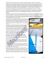
With the notched end of the pedestal facing down, test-fit an engine-mounting pod onto a composite
mounting pedestal as pictured at the top of the following page.
Aileron-servo opening Oval-shaped opening