


Copyright Maxford USA 2017
Page 4 of 12
S171201
VI. SAFETY PRECAUTIONS & ASSEMBLY TIPS
(IMPORTANT – READ THIS SECTION CAREFULLY BEFORE YOU BEGIN ASSEMBLY)
1.
This product should not be considered a toy, but rather a sophisticated, working model that functions
much like a full-scale airplane. Because of its performance capabilities, this product, if not assembled and
operated correctly, could cause injury to you or to spectators and damage to property. Maxford USA
provides you with a high-quality, thoroughly tested model airplane kit and written/photo assembly
instructions. However, the quality and capabilities of your finished model airplane depend on how you
assemble it, and your safety depends on how you use and fly it. Any testing or flying of this model airplane
is done entirely at your own risk.
2.
Assemble this model airplane according to these written/photo instructions. Do not alter or modify the
model beyond any assembly and/or power-system options covered in these instructions; doing so may
result in an unsafe or unworkable model. If the instructions differ from the photos, the written
instructions should be considered correct. If you have any question or concern about the instructions,
before you proceed with assembly of this product, contact your dealer or speak to a Maxford USA
customer service representative at 562-529-3988 (Monday through Friday, except national holidays,
9 AM to 5 PM Pacific Time).
3.
While this kit has been flight-tested to meet or exceed our rigid performance and reliability standards in
normal use, if you elect to attempt any high-stress flying, such as racing or aerobatics, or if you install a
larger power system than specified, you (the buyer or user of this product) are solely responsible for
taking any and all necessary steps to reinforce the high-stress points and/or substitute hardware that is
more suitable for such increased stresses.
4.
Throughout the lifetime of this model, use only the Maxford USA-recommended power system and a new
or well-maintained radio-control system with fully charged batteries.
5.
Before you begin assembly of this model airplane, study the instructions and test-fit each part to ensure
you fully understand the instructions and that no parts are missing, damaged or unsatisfactory. Some
parts may differ slightly from those pictured in this manual. Due to temperature and/or humidity
differences between the factory, our warehouse and your home or workshop, there may be some need for
slight adjustments to these instructions and/or to some mounting surfaces to ensure proper installation
and alignment. We recommend you contact us before attempting any such adjustment.
6.
It is your responsibility to install the receiver and to connect the R/C components in such a way that this
model passes all applicable safety/range tests and that the power system and controls operate correctly.
7.
Recheck the operation of this model before every flight to ensure all equipment is still operating correctly
and that the model remains structurally sound; also check all electrical, control and structural connections.
Do not fly without replacing any that you find damaged or worn.
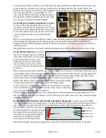
8.
To help ensure the security of your servo connections, we recommend using optional
Maxford USA servo-extension safety clips as pictured at the right. (For information
about safety clips see
http://www.maxfordusa.com/servoextensionsafetyclip.aspx
.)
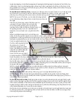
9.
Assemble any included or optionally installed
EZ-Link connectors as shown at the right.
When applying threadlock compound, do
NOT
glue the EZ-Link connector to the control arm
or mounting tab, and be careful to not let any
pushrods bind against any nearby surfaces.
10.
Use your radio system or a servo tester to center your servos before installation. (You may be interested
to learn more about servo testers at
http://www.maxfordusa.com/servo.aspx
.)
11.
String may be supplied to pull your servo’s leads and/or servo
extensions or other wiring through the wing or fuselage; however,
you may find it easier to use masking tape to temporarily attach
the end of the wire to a length of coat-hanger wire, then use the
wire to pull the lead through the airframe as pictured at the right.
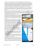
12.
After you determine each wood-screw’s location, drill a small guide
hole then apply thin CA adhesive to harden and strengthen the wood where the screws are to be installed.
Clamping bolt
Connector body
Control arm (or tab)
Washer
Mounting nut