background image


DP-20 WEB GUIDE CONTROLLER USER MANUAL


www.maxcessintl.com 

DP-20 

MI 1-862 1 F 


6-24 


6. 

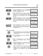
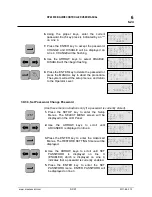
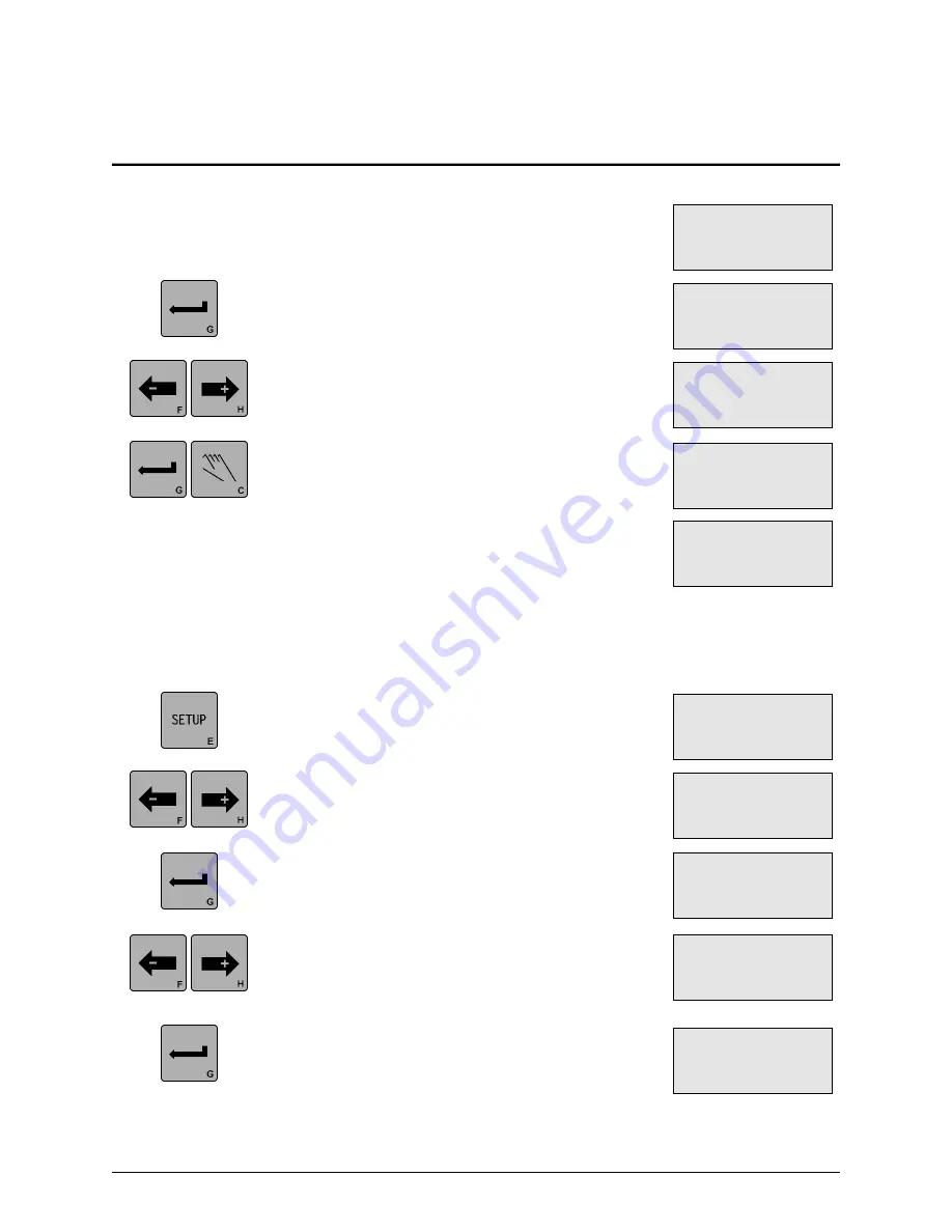
Using  the  proper  keys,  enter  the  current 
password. Each key press is indicated by an “*“ 
on Line 4. 


7.

 Press the ENTER key to accept the password. 

CHANGE  and  DISABLE  will  be  displayed  on 
Line 4. CHANGE will be flashing. 


8.

 Use  the  ARROW  keys  to  select  DISABLE. 

DISABLE will then begin flashing. 


9.

 Press the ENTER key to delete the password or 

press the MANUAL key to abort the procedure. 
The system will exit the setup menus, and return 
to the Operator Level. 


3X.3.3, Set Password, Change Password 


(Use these menu instructions only if a password is currently stored). 


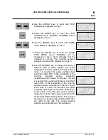
 1. 

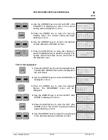
Press  the  SETUP  key  to  enter  the  Setup 
Menus.  The  SELECT  MENU  screen  will  be 
displayed on the LCD Panel. 


 2. 

Use  the  ARROW  keys  to  scroll  until 
ADVANCED is displayed on line 4. 


 3.

 Press  the  ENTER  key  to  enter  the  Advanced 

Menus. The RESTORE SETTINGS menu will be 
displayed.  


 4. 

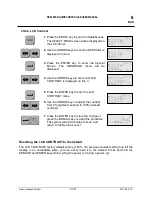
Use  the  ARROW  keys  to  scroll  until  SET 
PASSWORD 

is 

displayed 

on 

line 

3. 

(ENABLED)  which  is  displayed  on  Line  4, 
indicates that a password is currently enabled. 


 5. 

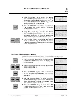
Press  the  ENTER  key  to  enter  the  SET 
PASSWORD  menu.  ENTER  PASSWORD  will 
be displayed on line 3. 


×           3A.1 
SETUP (MAN) 
SELECT MENU 
BASIC 

×           3A.3 
SETUP (MAN) 
SELECT MENU 
ADVANCED 

×        X3A.3.3 
SETUP (MAN) 
SET PASSWORD 
   (ENABLED) 

×        X3A.3.3 
SETUP (MAN) 
ENTER PASSWORD 


×        X3A.3.3 
SETUP (MAN) 
ENTER PASSWORD 
     ****** 

×      X3A.3.3.1 
SETUP (MAN) 
SET PASSWORD 
CHANGE   DISABLE 


×      X3A.3.3.1 
SETUP (MAN) 
SET PASSWORD 
CHANGE   DISABLE 

              3A 
         MANUAL 
×  -ãããããáÜÜÜÜ+ 
 

×         3A.3.1 
SETUP (MAN) 
RESTORE SETTINGS 


×       3A.3.3.5 
SETUP (MAN) 
 
 (NO PASSWORD) 

Содержание Fife Polaris DP-20

Страница 1: ...Polaris DP 20 Web Guide Controller User Manual EN Firmware version 1 13 and newer includes LCD Contrast Adjustment MI 1 862 1 F...

Страница 2: ...prior written consent of Maxc The information given in this User Manual is subject to change without notice We have compiled this User Manual with the greatest possible care and attention however the...

Страница 3: ...X 2 Servo Center Guide Point 5 1 2X 3 Measurement 5 2 6 SYSTEM SETUP MENUS AVAILABLE FROM MANUAL MODE 6 1 Basic Menus 6 1 3X 1 1 System Gain 6 1 3X 1 2 System Guide Point 6 1 3X 1 3 Guide Polarity 6 2...

Страница 4: ...ange 6 27 3X 3 7 Digital I O Enable Disable 6 28 3X 3 8 1 Test Signals Sensor Current 6 28 3X 3 8 2 Test Signals Toggle Outputs 6 29 3X 3 8 3 Test Signals Guide Test Mode 6 30 Language Menu 6 32 3X 4...

Страница 5: ...es superior guiding performance This controller is able to operate in a variety of sensor modes such as Fixed Sensor Center Guide or Edge Guiding from either edge Edge of Line or Center of Line Guidin...

Страница 6: ...www maxcessintl com DP 20 MI 1 862 1 F THIS PAGE INTENTIONALY LEFT BLANK...

Страница 7: ...Setup Menus SENSOR This key is used to select the sensor s to be used for monitoring the web position when the system is in Automatic mode Sensor selection is allowed in Manual and Servo Center modes...

Страница 8: ...current sensor selection is displayed in this line LINE 1 While in the setup menus the symbol of the current sensor selection is displayed in this line LINE 1 A command present on the Digital I O is...

Страница 9: ...X4 port and indicates Edge of Line guiding X4 port LINE 3 While at the Operator Level in Servo Center mode this line contains the Servo Center sensor symbol and also a bargraph indicating the signal l...

Страница 10: ...he value associated with the menu as defined in Line 3 If it is possible to modify the value it will be flashing LINE 4 While at the Operator Level in Automatic mode Servo Center mode or Manual mode i...

Страница 11: ...system will automatically exit the Setup Menus and return to the Operator Level While in Automatic Mode or Servo Center Mode the Gain and Guide Point changes are stored While in Manual Mode all change...

Страница 12: ...3X 3 8 3X 3 9 Restore Settings Backup Settings Set Password Set Output A Delay Set Output B Delay Loss of Null Output Range Digital I O X3 Test Signals Exit Menus LANGUAGE MENU 3X 4 1 Select Language...

Страница 13: ...nge increases The change is effective immediately but not stored 4 If desired press both of the ARROW keys simultaneously to reset the System Gain to 10 0 as indicated on line 4 5 Press the ENTER key...

Страница 14: ...effective immediately but not yet stored 5 If desired press both of the ARROW keys simultaneously to reset the System Guide Point to the center of the available range as indicated on line 4 6 Press th...

Страница 15: ...n Line 4 6 Use the ARROW keys to scroll to the desired Measurement menu Next in the list is the TACHOMETER The tachometer signal is displayed on Line 4 7 Use the ARROW keys to scroll to the desired Me...

Страница 16: ...P 20 is displayed on Line 4 11 If desired use the ARROW keys to scroll until EXIT MENUS is displayed on line 3 Pressing the ENTER key while this screen is displayed will exit the Measurement Menus and...

Страница 17: ...press both of the ARROW keys simultaneously to reset the Servo Center Gain to 5 0 as indicated on line 4 5 Press the ENTER key to store the change or press the MANUAL key to abort the change The syste...

Страница 18: ...s to scroll until MEASUREMENT is displayed on line 3 3 Press the ENTER key to view the Measurement menus The level of the guiding signal from the Left Edge Sensor Line Center if a line sensor is being...

Страница 19: ...2 1 0 9 Use the ARROW keys to scroll to the desired Measurement menu Next in the list is the FIRMWARE VERSION The version number of the firmware is displayed on Line 4 10 Use the ARROW keys to scroll...

Страница 20: ...www maxcessintl com DP 20 MI 1 862 1 F THIS PAGE INTENTIONALY LEFT BLANK...

Страница 21: ...e speed of the Gain change increases The change is effective immediately but not stored 5 If desired press both of the ARROW keys simultaneously to reset the System Gain to 10 0 as indicated on line 4...

Страница 22: ...ss both of the ARROW keys simultaneously to reset the System Guide Point to the center of the available range as indicated on line 4 7 Press the ENTER key to store the change or press the MANUAL key t...

Страница 23: ...nus The GAIN menu will be displayed 3 Use the ARROW keys to scroll until CALIBRATION is displayed on line 3 4 Press the ENTER key to enter the CALIBRATION menu SELECT SENSOR will be displayed on line...

Страница 24: ...l OR 10 If the contrast is not sufficient for guiding FAILED will be displayed on line 2 Press the MANUAL key to exit the setup menus and return to the Operator Level Repeat this procedure as necessar...

Страница 25: ...nsor such that the line to be guided is located within the opposite of the light spot see graphic at right The sensor signal is displayed on Line 3 Light Spot Line 9 Press the ENTER key If the contras...

Страница 26: ...see graphic at right The sensor signal is displayed on Line 3 Light Spot Line 7 Press the ENTER key WAIT will be displayed for a few seconds on line 4 of the LCD Panel Maintain the web position during...

Страница 27: ...ALIBRATION menu SELECT SENSOR will be displayed on line 3 5 Use the ARROW keys to select the Servo Center Sensor will be displayed on line 1 and X2 will be displayed on line 4 6 Press the ENTER key to...

Страница 28: ...will correspond to the sensor mode that is selected 1 Position the the edge of the web or the center or edge of the line in the center of the sensor field of view See the appropriate graphic at right...

Страница 29: ...etup is complete if it was not successful FAILED will be displayed on line 3 Press the MANUAL key to exit the setup menus and return to the Operator Level The Guide Point and Deadband are restored to...

Страница 30: ...to enter the Setup Menus The SELECT MENU screen will be displayed 2 Press the ENTER key to enter the BASIC Menus The GAIN menu will be displayed 3 Use the ARROW keys to scroll until POLARITY is displa...

Страница 31: ...Edge if a line sensor is being used The guiding signal is displayed on Line 4 This signal has been scaled by values which were determined during the Sensor Calibration procedure 6 Use the ARROW keys...

Страница 32: ...l EXIT MENUS is displayed on line 3 Pressing the ENTER key while this screen is displayed will exit the Measurement Menus and return to the Operator Level 13 Otherwise press the MANUAL key to exit the...

Страница 33: ...l exit the setup menus and return to the Operator Level 3X 2 2 Set Operation Mode Enable 1 Press the SETUP key to enter the Setup Menus The SELECT MENU screen will be displayed on the LCD Panel 2 Use...

Страница 34: ...LCD Panel 2 Use the ARROW keys to scroll until SPECIAL is displayed on line 4 3 Press the ENTER key to enter the Special Menus The DEADBAND menu will be displayed 4 Use the ARROW keys to scroll until...

Страница 35: ...the Operator Level 3X 2 3 Set Sensor Mode Enable Line Sensor 1 Press the SETUP key to enter the Setup Menus The SELECT MENU screen will be displayed on the LCD Panel 2 Use the ARROW keys to scroll un...

Страница 36: ...o the Operator Level 3X 2 4 Set Jog Enable 1 Press the SETUP key to enter the Setup Menus The SELECT MENU screen will be displayed on the LCD Panel 2 Use the ARROW keys to scroll until SPECIAL is disp...

Страница 37: ...Jog Polarity 1 Press the SETUP key to enter the Setup Menus The SELECT MENU screen will be displayed on the LCD Panel 2 Use the ARROW keys to scroll until SPECIAL is displayed on line 4 3 Press the E...

Страница 38: ...etup Menus The SELECT MENU screen will be displayed on the LCD Panel 2 Use the ARROW keys to scroll until SPECIAL is displayed on line 4 3 Press the ENTER key to enter the Special Menus The DEADBAND m...

Страница 39: ...W keys to scroll until SET SENSOR TYPE is displayed on line 3 The current sensor type is displayed on Line 4 5 Press the ENTER key to enter the SET SENSOR TYPE menu The current sensor type begins flas...

Страница 40: ...W keys to adjust the contrast from 0 lightest contrast to 100 darkest contrast 7 Press the ENTER key to store the change or press the MANUAL key to abort the procedure The system will exit the setup m...

Страница 41: ...e Backup Settings if YES was selected in step 5 or press the MANUAL key to abort the procedure The system will exit the setup menus and return to the Operator Level 3X 3 2 Backup Settings This procedu...

Страница 42: ...stored 1 Press the SETUP key to enter the Setup Menus The SELECT MENU screen will be displayed on the LCD Panel 2 Use the ARROW keys to scroll until ADVANCED is displayed on line 4 3 Press the ENTER k...

Страница 43: ...rd Delete Password Use these menu instructions only if a password is currently stored 1 Press the SETUP key to enter the Setup Menus The SELECT MENU screen will be displayed on the LCD Panel 2 Use the...

Страница 44: ...P key to enter the Setup Menus The SELECT MENU screen will be displayed on the LCD Panel 2 Use the ARROW keys to scroll until ADVANCED is displayed on line 4 3 Press the ENTER key to enter the Advance...

Страница 45: ...re enter the desired new password The password must be the same as previously entered If a different password is entered WRONG PASSWORD will be displayed 12 Press the ENTER key to store the new passwo...

Страница 46: ...ress the MANUAL key to abort the change The system will exit the setup menus and return to the Operator Level 3X 3 5 Set Output B Delay 1 Press the SETUP key to enter the Setup Menus The SELECT MENU s...

Страница 47: ...Panel 2 Use the ARROW keys to scroll until ADVANCED is displayed on line 4 3 Press the ENTER key to enter the Advanced Menus The RESTORE SETTINGS menu will be displayed 4 Use the ARROW keys to scroll...

Страница 48: ...yed on Line 4 5 Press the ENTER key to enter the DIGITAL I O menu The current setting will begin flashing 6 Use the ARROW keys to scroll to the desired setting ENABLED or DISABLED 7 Press the ENTER ke...

Страница 49: ...ge of the bargraph and the numerical value is 20mA 7 If necessary use the ARROW keys to toggle to the desired sensor as indicated on line 3 The value of the sensor signal is shown on line 4 8 Press th...

Страница 50: ...e OUT B between ON and OFF 9 Press the MANUAL key to exit the setup menus and return to the Operator Level No settings are stored and control of the outputs is returned to normal 3X 3 8 3 Test Signals...

Страница 51: ...d the guide oscillates back and forth within 80 of the bandwidth of the currently selected sensor simulating instantaneous 80 Guide Point Shifts If mode 2 is selected the guide oscillates back and for...

Страница 52: ...scillator is running will pause the oscillation PAUSED will be displayed on line 2 The unit will remain paused until another command is issued 11 Pressing the AUTOMATIC key will resume the oscillator...

Страница 53: ...CUSTOM is displayed 3 Press the ENTER key to enter the Custom Menus The ASC CONTROL menu will be displayed The current setting is displayed on line 4 4 If necessary press the SENSOR key to select the...

Страница 54: ...e ARROW keys to adjust the negative ASC limit value if desired Press both ARROW keys simultaniously to reset the negative ASC value to the default 90 if desired 8 Press the ENTER key to switch to the...

Страница 55: ...e 4 3 Press the ENTER key to enter the Custom Menus The ASC CONTROL menu will be displayed 4 Use the ARROW keys to scroll until SET ASC SOURCE is displayed on lin 3 The current setting is displayed on...

Страница 56: ...LINE EDGE 1 1 0 SENSOR EDGE CENTER 1 1 1 Inputs 4 5 are used to provide Jogs while in Manual and Servo Center modes and RGPC functions while in Automatic mode Sensor selection is allowed in Manual and...

Страница 57: ...www maxcessintl com DP 20 MI 1 862 1 F THIS PAGE INTENTIONALY LEFT BLANK...

Страница 58: ...l Lock command is detected on the Parallel Port an asterisk surrounded by parentheses is displayed on line 1 of the LCD Panel 11 When any Setup Menu is entered commands on the Parallel Port for Operat...

Страница 59: ...www maxcessintl com DP 20 MI 1 862 1 F THIS PAGE INTENTIONALY LEFT BLANK...

Страница 60: ...connectors 1X 1 System Gain or 3X 1 1 System Gain Actuator moves the wrong direction in Automatic mode Guide Polarity is set incorrectly or Incorrect sensor mode selected Change Guide Polarity Select...

Страница 61: ...o check for bad cables Re apply power If problem persists the unit must be repaired AC POWER FAIL fault 004 A failure of the AC Power was detected The unit will automatically reset If the fault persis...

Страница 62: ...to exit the fault screen Cycle the power to the unit If the fault persists the unit must be repaired EEPROM BUSY fault 011 This fault indicates that the EEPROM was busy when a memory write was attemp...

Страница 63: ...7 001 Motor 14K GAB 1 GAG 2 PT 200 1 6A MOTOR 16 9K 1 3 A 534734 001 Motor 16 9K GAB 1 GAG 2 PT 200 0 4A MOTOR 20 5K 0 4 A 66356 001 Motor 66356 002 Motor 20 5K NarroWeb 25 1 0A MOTOR 44 2K 1 0 A 6531...

Страница 64: ...ate Weight 1 6 Kg 3 5 lbs Inputs and Outputs Electromechanical Actuator Maximum 39 W at 30 V Hydraulic Servo Valve 50 mA With or without Lockout Valve Max 39 W at 24 V or 48 V MPA with MPA Lockout Sig...

Страница 65: ...14 m 46 ft RGPC 40 100 m 330 ft AMERICAS Tel 1 405 755 1600 Fax 1 405 755 8425 sales maxcessintl com www maxcessintl com EUROPE MIDDLE EAST AND AFRICA Tel 49 6195 7002 0 Fax 49 6195 7002 933 sales ma...

Отзывы: