9
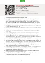
INSTALLATION OF THE DUST COLLECTOR
Watch the video for detailed installation instructions:
youtu.be/YWRp8qL5NqU
QR code link
How to enable the subtitles in the video:
• Press the gear wheel symbol and in the drop down menu click
Subtitles.
• In the next menu you can choose the language of subtitles
1. Disconnect the air duct (3) from the nail dust collector.
2. Place the nail dust collector on the tabletop. Choose the direction in which
it will be installed. We recommend installing the nail dust collector with the
hexagon faces towards the nail artist so that the MAX logo is on the left side
of the nail artist. When installing it in the described way, the switch will be on
the side of the suction zone.
3. Place the stencil on the tabletop. Adjust the stencil location and secure it
with the adhesive tape.
4. Drill through holes. The holes diameter is 1-2 mm. The suggested drilling
points are marked on the stencil.
5. Enlarge the holes with a drill of a larger diameter. The recommended
diameter is 6-7 mm.
6. Using a fret saw, cut out a hole in the desk top that repeats the contours of
the figure on the pattern. Clean the desk top from dust.
7. Insert the dust collector into the cut hole, while holding the dust collector by
side facets of the cover. To do this, you need to make a pendulum motion:
insert one part, move the dust collector to the side, insert the second part.
8. Remove the dust collector from the desk top. Degrease the installation place
of the dust collector.
9. Carefully remove the protective layer of double-sided adhesive tape from
the bottom part of the cover. For additional fixation of the dust collector the
glue can be carefully applied to the lower part of the top cover instead of
nails (not included).
10. Install the dust collector. Try not to allow the adhesive tape to stick earlier
than the moment the dust collector is placed in its intended position.
11. By pressing slightly on the upper cover install it in its final position.
When using glue, let it dry, following the recommendations of the glue
manufacturer.
12. Install the filter bag on the air tube (see “Usage” section for more details).
Close it with locking plate.
13. Install the air tube. Lower outlet pipe can rotate after its installation around
its axis (with force applied). This means it can be turned around if necessary.
ENG
Содержание Ultimate VII
Страница 1: ...MAX ULTIMATE VII BUILT IN USER S GUIDE...
Страница 3: ...3 MAX ULTIMATE VII MAX Ultimate VII 1 2 3 1 2 3 4 5 Max Pro 6 1 RUS...
Страница 4: ...4 youtu be YWRp8qL5NqU QR 1 3 2 MAX 3 4 1 2 5 6 7 6 7 8 9 10 11 12 RUS...
Страница 5: ...5 13 1 3 i ii 2 3 4 220 6 1 5 6 4 1 5 RUS...
Страница 7: ...7 i max4u ru 1 5 15000 20000 RUS...
Страница 38: ...38 SR MAX ULTIMATE VII MAX Ultimate VII 1 2 3 1 2 3 4 5 Max Pro 6 1...
Страница 39: ...39 SR youtu be YWRp8qL5NqU QR 1 3 2 MAX 3 4 1 2 mm 5 6 7 mm 6 7 8 9 10 11 12 13...
Страница 40: ...40 SR 1 3 I II 2 3 4 220 V 6 5 6 4 1 5 cm...
Страница 42: ...42 SR...


