


5
© Copyright Century UK Limited 2012 www.centuryuk.com
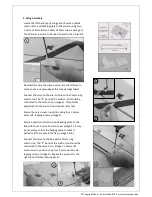
1. Wing Assembly
Locate the left hand (port) wing panel. Secure a plastic
control horn and backing plate to the aileron using two
1.5mm x 15mm & two 1.5mm x 20mm screws, (image 1).
The 20mm screws are to be used closest to the hinge line.
Electrically centre the aileron servo, (do not attempt to
move any servos manually as this may damage them).
Connect the servo to the aileron horn with a 75mm long
control rod. The “Z” bend of the control rod should be
connected to the servo horn, (image 2). This permits
adjustment to the clevis if required at a later time.
Secure the servo cover in position using four 1.5mm x
6mm self- tapping screws, (image 3).
2
3
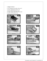
Secure a plastic control horn and backing plate to the
flap with four 1.5mm x 15mm screws, (image 4). It may
be necessary to trim the backing plate to make it
perfectly fit the recess in the flap, (image 5 & 6).
Connect the servo to the flap with a 75mm long
control rod. The “Z” bend of the control rod should be
connected to the servo horn, (image 7). Secure the
servo cover in position using four 1.5mm x 6mm self-
tapping screws, (image 8). Repeat the process for the
right hand (starboard) wing panel.


