Max-Thrust B-17 Скачать руководство пользователя страница 10

10 


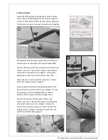
Remove one nut from each motor shaft, 

leaving the remaining nut tightened at the 

end of the thread, (image23). 

Slide the propeller onto the shaft and fix 

securely in position with the remaining nut, 

(image 24). 


Note:


It is essential that the propellers are 

securely fixed. Failure to do so could result 

in serious damage or injury. 


The scale effect propeller nuts are simply 

screwed onto the motor shafts, (image 25). 

Please remember that the threads on the 

shafts are handed!  


Propellers (continued) 
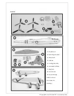
23 

24 

25 

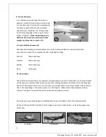
7. Battery Installation 

Your flight batteries, (not included) need 

to be firmly secured in the battery 

compartment to prevent them from 

moving in flight, (image 26). The model 

includes one battery positioning strap, 

however the batteries will require an 

additional method of fixing to provide 

adequate security. Because most 

experienced pilots will have a preferred 

method of battery retention, this has not 

been included with the model. We 

recommend the use of self-adhesive 

“Velcro” combined with additional 

straps. 

    Image shows 2 x Power-Tech 3350mAh 4S Li-Po’s 

© Copyright Century UK Limited 2012   www.centuryuk.com


26 

Содержание B-17

Страница 1: ...1 B 17 R C SPORT SCALE AIRCRAFT ASSEMBLY AND INSTRUCTION MANUAL Copyright Century UK Limited 2012 www centuryuk com...

Страница 2: ...ipment with this model Copyright Century UK Limited 2012 www centuryuk com Disclaimer 1 This radio controlled model is not a toy Used incorrectly it is capable of inflicting serious injury to persons...

Страница 3: ...tain you will enjoy your new model please take the time to read this manual thoroughly and understand its contents completely prior to commencing assembly Copyright Century UK Limited 2012 www century...

Страница 4: ...etracting Tail wheel 3 Plastic Parts 4 Adhesive 5 Fuselage Assembly 6 Horizontal Tail Plane 7 Wing Spar 8 Control Leads 9 Screws Fixings 10 Servo Covers 11 Vertical Fin 12 Wings 7 8 9 10 11 12 Copyrig...

Страница 5: ...should be connected to the servo horn image 2 This permits adjustment to the clevis if required at a later time Secure the servo cover in position using four 1 5mm x 6mm self tapping screws image 3 2...

Страница 6: ...rvo to the control horn using a 75mm control rod The Z bend of the control rod should be connected to the servo horn image 13 Secure the servo cover in position using four 1 5mm x 6mm self tapping scr...

Страница 7: ...heel unit image 19 Route the other end of this lead through the fuselage towards the wing area Secure the retracting tail wheel unit in position using the four M3 x 10mm self tapping screws image 20 C...

Страница 8: ...recommend that the adhesive is used sparingly Using a cocktail stick makes accurate application of the adhesive easy Apply sparingly Cockpit screen Rear screen Forward gun turret Rear gun turret Fron...

Страница 9: ...You will note they are numbered 1 4 make certain they are connected accordingly 1 1 2 2 etc The two servo type leads with only black and red wired from the ESCs supply power to the wing lights Connect...

Страница 10: ...fts are handed Propellers continued 23 24 25 7 Battery Installation Your flight batteries not included need to be firmly secured in the battery compartment to prevent them from moving in flight image...

Страница 11: ...commend the balance point of the model complete with batteries should be 125 135mm back from the leading edge of the wing for initial flights image 27 Note Depending on the batteries used it may be ne...

Отзывы: