INSTALLATION MANUAL CT550
7
7.
HYDRAULIC (general remarks)
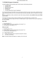
A typical installation of the hydraulic power thruster requires the following elements:
oil reservoir/tank
hydraulic pump
directional control valve
hydraulic motor
circuit piping
oil cooler (depending on type of installation)
The oil reservoir/tank with return filter and suction strainer should be as close to the pump as possible and on
charge. Meaning that the level of the oil should be above the pump, preferably with the oil tank above the water
line.
For future maintenance, make sure that the return filter is easily accessible.
An isolation valve can be fitted
to the suction.
The pump can be driven only by internal combustion engine (crankshaft pulley or gearbox PTO).
For an internal combustion engine with fixed or variable speed, 2 types of pumps can be used, depending on
the unit to be fitted:
Direct PTO:
1. Fixed flow pump (***)
2. Variable displacement pump, depending on the model (**) (*)
3. Fixed flow pump with bypass (**) (*)
PTO with clutch:
1. Fixed flow pump (**) (*)
2. Variable displacement pump depending on the model (**) (*)
3. Fixed flow pump with bypass (**) (*)
(***) always require oil cooler
(**) require oil cooler when time of operation exceeds 15 minutes,
(*) oil cooler not necessary
Note:
The above choices also depend on capacity of the oil tank etc.
Содержание CT550
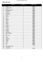
Страница 10: ...INSTALLATION MANUAL CT550 10 10 CT550 PART LIST ...
Страница 13: ...INSTALLATION MANUAL CT550 13 12 HYDRAULIC DIAGRAM ...
Страница 19: ...18 ...


