INSTALLATION MANUAL CT550
6
4.
THE HYDRAULIC MOTOR
Insert the lower drive coupling onto the leg drive shaft (lightly grease the shaft before doing this).
Then position the motor and tighten the 4 x 12 mm to 80Nm.
IMPORTANT:
Please note that the above coupling might need to be adjusted if any other tunnel than a Max
Power tunnel (thickness 12-14mm) is used.
The top and bottom coupling pieces should fit tightly together to ensure maximum gripping between them.
Check that the propellers turn freely and that there is no tight spot. A certain amount of resistance is normal
from the motor. When all is assembled recheck the tightness of all the motor bolts.
NOTE:
The coupling on the motor side is in place when delivered, do not touch this.
5.
PROPELLERS
The positioning of the propellers is indicated at the end on chapter
“PROPELLER ASSEMPLY”.
6.
PROTECTION GRILLS
With a shallow tunnel installation, we recommend that you protect the propellers by fitting horizontal protection
grills. These grills will however modify thruster performance.
Содержание CT550
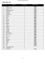
Страница 10: ...INSTALLATION MANUAL CT550 10 10 CT550 PART LIST ...
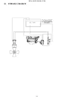
Страница 13: ...INSTALLATION MANUAL CT550 13 12 HYDRAULIC DIAGRAM ...
Страница 19: ...18 ...


