background image


SmartDrive

  User’s Manual         

7

Drive Unit Attachment and Removal

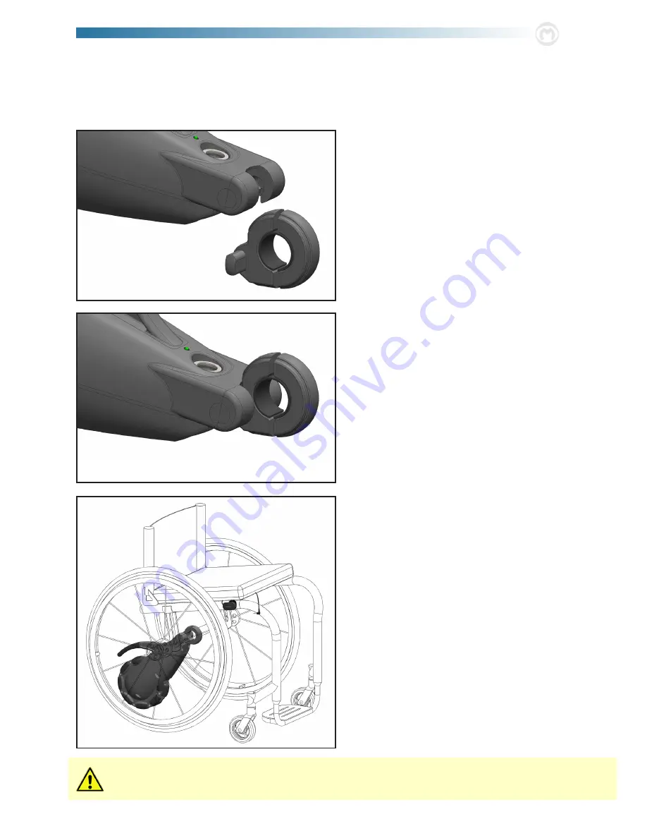
The SmartDrive drive unit is designed to easily attach to the adaptive clamp so the user can quickly attach/remove whenever 

desired or necessary. Use of the handle and the drop and lock interaction make attaching the SmartDrive simple for all users.

1. 

To attach the drive unit to the wheelchair, align the 

flats in the adaptive clamp with the receiving slots on 

the front, underside of the unit body [the drive unit will 

be angled slightly higher than horizontal]. Lower the 

receiving end of the drive unit over the extrusions of the 

clamp. 

2. 

Rotate the unit downward to pivotally attach the drive 

unit to the clamp, and consequently the wheelchair. 

3. 

Under its own weight, the omni-wheel end of the drive 

unit rests on the ground between the rear wheels of the 

wheelchair.

Remove the unit by firmly grasping the handle and perform-

ing these steps in reverse order, first rotating upwards then 

lifting the receiving slots off the adaptive clamp.

 Never attempt to remove the drive unit from the clamp while still seated in the wheelchair. This presents a serious    

              risk of tipping over and injury.

Содержание smartdrive mx1+

Страница 1: ...User s Manual 5425 crossings boulevard nashville tn 37013 usa p 800 637 2980 f 888 411 9027 www max mobility com max mobility llc SmartDrive MX1 Rev MX1 0 UM A SL Wheelchair Power Assist...

Страница 2: ......

Страница 3: ...rive Unit Model SD1 0 Overall length 14 3 in Overall width 5 5 in Overall height 9 5 in Weight 11 lbs Omni wheel diameter 7 6 in Omni wheel width 2 8 in Battery Unit Model SB1 0 Battery type Lithium I...

Страница 4: ...et Up 5 Adaptive Clamp Mounting 5 Button Mounting 6 Drive Unit Attachment and Removal 7 Battery Unit Clipping 8 3 Operating the SmartDrive 10 Power Assist ON OFF 10 Switching Between States 10 Power A...

Страница 5: ...exist cease the use of the SmartDrive and contact Max Mobility for service further instruction Any contrary use to the directions of this user s manual to the recommendations of one s mobility equipm...

Страница 6: ...to the SmartDrive will void the may tip over backwards or sideways Do not tip or wheel your wheelchair without assistance unless you are highly skilled Using Anti Tippers substantially reduces your ri...

Страница 7: ...in close vicinity to sources of radio waves There are three categories that EMI sources fall under 1 Long Range Transceivers These are sources of strong radio waves including commercial radio and TV b...

Страница 8: ...1 3 5 4 6 7 11 8 9 10 13 14 15 2 2 12 16 17 4 max mobility...

Страница 9: ...positioned midway between the two rear wheels of the wheelchair on the axle receiving tube The two 2 screws should be tightened to 4 ft lbs fix ing it in this position and orientation Failure to do t...

Страница 10: ...hair The plug cable should hang over the left front side of the seat as shown below 2 Use the provided velcro strips to strap down the but ton cables to the upholstery running the right button cable a...

Страница 11: ...t will be angled slightly higher than horizontal Lower the receiving end of the drive unit over the extrusions of the clamp 2 Rotate the unit downward to pivotally attach the drive unit to the clamp a...

Страница 12: ...t tery housing With the Button plug wire to the side slide the unit back until the front surface of the upholstered seat is making contact with the handle 3 Slide the battery back as far back as possi...

Страница 13: ...de The connector will automatically lock into the plug when it is fully pushed in Use extreme caution when attempting to plug or unplug the connector while seated in the wheelchair This presents a ser...

Страница 14: ...d Outdoor Mode This second mode is ideal for special times when easy power activation is needed such as on inclines and thick carpet and when environmental conditions are more diverse Switc ing betwee...

Страница 15: ...or is powering at the lower speed by performing another harder push This Easy Start activation in Outdoor Mode is especially useful when on a steep hill incline ramp etc where it might be dif ficult t...

Страница 16: ...significantly longer cycle life and faster charging rate than standard lithium ion cells The green LED on the top of the buttons is used to indicate the battery charge level In any mode or state with...

Страница 17: ...nty Max Mobility offers a 2 year warranty against manufacturing defects Max Mobility s obligation under this warranty shall be limited to repairing or providing replacement of part s which are found t...

Страница 18: ...5425 crossings boulevard nashville tn 37013 usa p 800 637 2980 f 888 411 9027 www max mobility com...

Отзывы: