Matrix U5x-05 Скачать руководство пользователя страница 7

4

CHAPTER 2: IMPoRTANT SAfETy INfoRMATIoN

2.2 ElECTRICAl REqUIREMENTS

110 V UNITS 

All Matrix 3x, 5x, 7xe and 7xi 110 V bikes require the use of a 100-125 V, 60 Hz and a 15 A 

“Dedicated Circuit”, with a non-looped (isolated) neutral/ground for power. This outlet should be a 

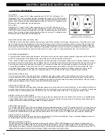
NEMA 5-15R and have the same configuration as the plug. No adapter should be used with this 

product. These bikes can be daisy-chained together with up to 4 units per 15 A dedicated circuit. 

Matrix daisy-chain cord adapters are sold separately.
220 V UNITS 

All Matrix 3x, 5x, 7xe and 7xi 220 V bikes require the use of a 216-250 V, 50 Hz and a 15 A 

“Dedicated Circuit”, with a non-looped (isolated) neutral/ground for power. This outlet should be a 

NEMA 6-15R and have the same configuration as the plug. No adapter should be used with this 

product. These bikes can be daisy-chained together with up to 4 units per 15 A dedicated circuit. 

Matrix daisy-chain cord adapters are sold separately. 

DEDICATED CIRCUIT AND ELECTRICAL INFO
A “Dedicated Circuit” means that each outlet you plug into should not have anything else running on that same circuit. The easiest way to verify 

this is to locate the main circuit breaker box, and turn off the breaker(s) one at a time. Once a breaker has been turned off, the only thing that 

should not have power to it are the units in question. No lamps, vending machines, fans, sound systems, or any other item should lose power 

when you perform this test. Non-looped (isolated) neutral/grounding means that each circuit must have an individual neutral/ground connection 

coming from it, and terminating at an approved earth ground. You cannot “jumper” a single neutral/ground from one circuit to the next.

ELECTRICAL REQUIREMENTS
For your safety and to ensure good unit performance, the ground on this circuit must be non-looped (isolated). Please refer to NEC article 210-21 

and 210-23. Any alterations to the standard power cord provided could void all warranties of this product.
The 3x, 5x and 7xe bikes are designed to be self-powered and do not require an external power supply source to operate.  Without an external 

power supply, the console’s start-up time may be delayed. Add-on TV’s and other console accessories will increase the time needed for start-up. 

An external power supply will ensure power is provided to the console at all times and is recommended when add-on accessories are used. 
For units with an integrated TV (like the 7xe and 7xi), the TV power requirements are included in the unit. An RG6 coaxial cable with ‘F Type’ 

compression fittings on each end will need to be connected to the cardio unit and the video source. Additional power requirements are not 

needed for the add-on digital TV (3x and 5x). For units with an add-on PCTV (3x and 5x), the TV power requirements are separate.

GROUNDING INSTRUCTIONS 

The unit must be grounded. If it should malfunction or breakdown, grounding provides a path of least resistance for electric current to reduce 

the risk of electric shock. The unit is equipped with a cord having an equipment-grounding conductor and a grounding plug. The plug must be 

plugged into an appropriate outlet that is properly installed and grounded in accordance with all local codes and ordinances. If the user does not 

follow these grounding instructions, the user could void the Matrix limited warranty.

ADDITIONAL ELECTRICAL INFO 

In addition to the dedicated circuit requirement, the proper gauge wire must be used from the circuit breaker box, to each outlet that will have the 

maximum number of units running off of it. If the distance from the circuit breaker box to each outlet, is 100 ft (30.5 m) or less, then 12 gauge wire 

should be used. For distances greater than 100 ft (30.5 m) from the circuit breaker box to the outlet, a 10 gauge wire should be used.

ENERGY SAVING / LOW-POWER MODE 

All units are configured with the ability to enter into an energy saving / low-power mode when the unit has not been in use for a specified period 

of time. Additional time may be required to fully reactivate this unit once it has entered the low-power mode. This energy saving feature may be 

enabled or disabled from within the ‘Manager Mode’ or ‘Engineering Mode.

ADD-ON PCTV (3X AND 5X)  

A 15 A or 20 A “Dedicated Circuit” with a non-looped (isolated) neutral/ground is required.  Each PCTV requires at least 1.2 A of current. No more 

than 12 PCTVs should be used for each 15 A circuit and no more than 16 PCTVs should be used for each 20 A circuit. The power outlet should 

have the same configuration as the plug. No adapter should be used with this product. An RG6 coaxial cable with ‘F Type’ compression fittings 

will need to be connected between the video source and each add-on PCTV unit.  See the PCTV Manual for web connection requirements.

ADD-ON DIGITAL TV (3X AND 5X) 

Additional power requirements are not needed for the add-on digital TV. An RG6 coaxial cable with ‘F Type’ compression fittings will need to be 

connected between the video source and each add-on digital TV unit.

North American power cord plugs shown.  

Depending on your country, the plug type may vary.

BATTERY CHARGING (3X AND 5X)  

The bike saves its batter charge by moving into a shutdown mode whenever PEDAL FASTER appears on the display.  If the user does not 

maintain a pedal rate of 40 RPM or higher, a 30 second shutdown process begins.  When the battery voltage is low, LOW BATTERY appears 

on the display.  This means it is time to recharge the battery.  If the battery must be charged, use the optional power adapter charging unit.  The 

charger should be connected to the bike for a minimum of eight hours to ensure a thorough charge.  

Содержание U5x-05

Страница 1: ...U 5 x 0 5 B I K E S E R V I C E M A N U A l...

Страница 2: ...7 Workout Setup Steps Constant Watts 10 CHAPTER 5 Manager MODE 5 1 Using Manager Mode 11 5 2 Manager Mode Overview 11 CHAPTER 6 ENGINEERING MODE 6 1 Using Engineering Mode 12 CHAPTER 7 SERVICE MODE 7...

Страница 3: ...lacement 42 9 13 Lower Control Board Replacement 43 9 14 Battery Replacement 44 9 15 Drive Belt Replacement 45 9 16 Generator Replacement 46 9 17 Rear Stabilizer Replacement 47 9 18 Front Stabilizer R...

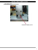
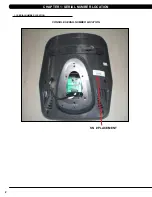
Страница 4: ...1 1 1 Serial Number Location Chapter 1 Serial Number Location fRAME Serial number location...

Страница 5: ...2 console serial number location 1 1 Serial Number Location Chapter 1 Serial Number Location SN PLACEMENT...

Страница 6: ...eep hands away from moving parts If the item cannot be reached contact a Matrix authorized dealer for assistance Never operate the unit if it is damaged not working properly when it has been dropped o...

Страница 7: ...5x For units with an add on PCTV 3x and 5x the TV power requirements are separate GROUNDING INSTRUCTIONs The unit must be grounded If it should malfunction or breakdown grounding provides a path of le...

Страница 8: ...ly scheduled cleaning YOU WILL NEED Mild dish soap and water mixture in a spray bottle 10 1 water to soap ratio Lint free 100 cotton cleaning cloths or Microfiber cleaning cloths Vacuum Shop Vac with...

Страница 9: ...lable on the Matrix web site at www matrixfitness com DAILY MAINTENANCE ITEMS 1 Look and listen for loose fasteners unusual noises and any other indications that the equipment may be in need of servic...

Страница 10: ...tion UP DOWN TIME Easy information and time adjustment STOP Ends workout and shows workout summary data NUMBER KEYPAD Workout data input for workout setup Level adjustment during workout COOL DOWN Put...

Страница 11: ...display will read 3 2 1 Begin and then the program will start 4 3 workout setup steps fat burn ROLLING HILLS The Rolling Hills program is a level based program that automatically adjusts the resistan...

Страница 12: ...next level The test could take upwards of 30 minutes for very fit individuals Once the test ends a recovery period cool down will begin and the user s results are calculated and displayed Results are...

Страница 13: ...an grab these sensors in any program to view your current heart rate 1 Start pedaling and press the HEART RATE key Then press ENTER 2 Select Age by using the UP or DOWN LEVEL keys and press SELECT 3 S...

Страница 14: ...min Maximum Time Setting Workout time when GO is pressed or when no time is selected during program set up Default Level 1 1 30 Starting resistance when GO is pressed or when no resistance is selected...

Страница 15: ...his blank Second Layer YY MM nnnnn YY is the year 11 12 MM is the month e g 08 09 10 nnnnn is the actual serial number Use the UP DOWN LEVEL keys to navigate the layers and the number keys to input th...

Страница 16: ...ally sets the Accumulated Distance and Time Service 4 CSafe RF Test Press the ENTER key to test CSAFE Press the ENTER key again to test the RF Service 5 Error Log Shows the last 10 errors Press and LE...

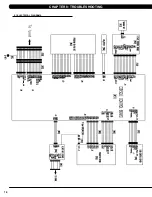
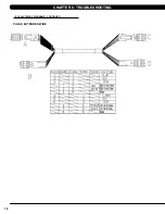
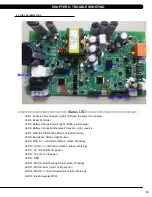
Страница 17: ...14 8 1 Electrical Diagrams Chapter 8 Troubleshooting...

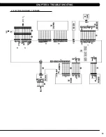
Страница 18: ...15 Chapter 8 Troubleshooting 8 1 electrical diagramS CONTINUED...

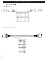
Страница 19: ...16 8 1 Electrical Diagrams CONTINUED Chapter 8 Troubleshooting MCB POWER Wire Digital Communication Wire...

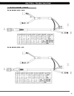
Страница 20: ...17 Chapter 8 Troubleshooting 8 1 Electrical Diagrams CONTINUED pulse sensor wire rIGHT pulse sensor wire lEFT...

Страница 21: ...18 8 1 Electrical Diagrams CONTINUED Chapter 8 Troubleshooting PULSE extended WIRE...

Страница 22: ...onnection Reverse Protection Light reverse LED7 MCU B LCB Working Status Flash Working LED8 Resistance Offset Light Normal LED9 MCU A B Communication Flash Working LED10 UCB LCB Communication Flash Wo...

Страница 23: ...4A0 error check the LCB LED10 status LED10 blinking Turn off power and after 3 seconds turn on power again If console also show the 04A0 re install UCB software again If this does not resolve the issu...

Страница 24: ...blinking Turn off power and after 3 seconds turn on power again If the console shows the 04A0 error skip to Step 2 LED10 off Check the connection of the digital communication wire at the UCB and LCB...

Страница 25: ...LCB battery voltage is less than 6 VAC 2 SOLUTION 1 Please check the battery wire connection between the battery and LCB Figure A 2 Check the battery voltage Figure B if it is less than 6 V please plu...

Страница 26: ...0441 1 SYMPTOM 02B4 Resistance type error 03A8 Control settings on the machine does not match the model setting 02AB Machine Type Error 0441 Correct packet but LCB without the function LCB does not su...

Страница 27: ...net over current 01AF Electro magnet disconnected 2 SOLUTION 1 Check if the Electro magnet is short circuited or open Figure A If the resistance data shows a short open ohms or is outside the range of...

Страница 28: ...OR CODE 01B4 1 SYMPTOM 01B4 Battery connection reverse protection 2 SOLUTION 1 Check the battery wire connection between the battery and LCB Figure A 2 Check the battery voltage Figure B If there is n...

Страница 29: ...B Figure A Figure B NO RESISTANCE ISSUES 1 SYMPTOM No resistance 2 SOLUTION 1 Check the resistance wire connection between the ECB and LCB Figure A 2 Check if the resistance is open Figure B If there...

Страница 30: ...onsole from the unit and verify continuity of the HR grip wiring With a multi meter set for ohms place one prong on the HR grip wiring coming up the console mast Figure C and the other on the appropri...

Страница 31: ...ess room power b If LED9 is still not lit check the incoming AC power to the LCB If the incoming power is not correct replace the power cord c Replace the LCB if all power components are OK and there...

Страница 32: ...ER c Test the affected keypad If the keypad works in the keypad test it may not be a functioning key in the program used for testing it 2 Check the connections of the keypad at the UCB a Remove the co...

Страница 33: ...console and remove the console Figure B 3 Reinstall the wire connections to the new console 4 Carefully push the wires into the console and mast until they are clear of the console mast connection an...

Страница 34: ...REPLACEMENT Chapter 9 Part Replacement guide 1 Remove the 4 screws holding the cup holder to the console mast Figure A 2 Remove the cup holder Figure B 3 Reverse Steps 1 2 to install a new cup holder...

Страница 35: ...l to support the handlebar Figure A 3 Carefully pull the wires from the console mast until the connectors are showing and then disconnect the 2 wires from the handlebar and remove the defective handle...

Страница 36: ...moved using a Phillips screwdriver from the underside of the bar 2 Once the screws are removed lift the part carefully then disconnect any wire connections to fully remove the part This includes any r...

Страница 37: ...ay keypad is 1 Turn off power and disconnect the cord from the machine 2 Remove the console as outlined in Section 9 1 3 Remove the back cover of the console Figure A 4 Unplug and remove the faulty ov...

Страница 38: ...tch the overlay to the cutout on the console Figure G 10 Press down on the corners of the overlay to keep it in place then remove the protective film Figure H I 11 Once the overlay is in the correct p...

Страница 39: ...right side pedal the threads are normal For the left side pedal the threads are reversed the pedal turns off counterclockwise 2 Remove the pedal Figure B 3 Reverse Steps 1 2 to install a new pedal NOT...

Страница 40: ...to the drive axle set Figure A 2 The crank can be removed Figure B 3 Reverse Steps 1 2 to install a new crank axle set NOTE Torque the bolt removed in Step 1 to 80 N m 800 kgf cm 4 Test the bike as ou...

Страница 41: ...Remove the silver cover Figure B 3 Remove the 2 screws that hold the grey cover to the frame Figure C 4 Remove the black cover Figure D 5 Reverse Steps 1 4 to install new shrouds 6 Test the bike for...

Страница 42: ...the front shroud as outlined in Section 9 8 4 Remove the 9 screws holding the left side cover in place Figure A 5 Remove the 6 screws holding the right side cover in place Figure B 6 Figure C shows bo...

Страница 43: ...he 4 screws holding the console mast to the frame Figure A 6 Pull the wires out the bottom of the console mast and remove the mast Figure B 7 Reverse Steps 1 6 to install new console mast NOTE When in...

Страница 44: ...ment Figure B Figure A 1 Remove the 4 screws holding the seat pad to the seat post Figure A 2 Lift the seat pad away from the seat post Figure B 3 Reverse Steps 1 2 to install a new seat pad Chapter 9...

Страница 45: ...vers as outlined in Section 9 8 2 Remove the 4 screws that hold the seat post set to the frame Figures A B 3 Remove the seat post set Figure C 4 Reverse Steps 1 3 to install a new seat post set Figure...

Страница 46: ...gure B and remove the lower board 4 Reverse Steps 1 3 to install a new lower board Figure C shows the connections at the board 5 Test the bike for function as outlined in Section 9 20 figure a figure...

Страница 47: ...ve the LCB as outlined in Section 9 13 3 Disconnect the 2 wires from the battery Figure A 4 Disconnect the 2 cable ties from the battery bracket Figure B 5 Remove the battery Figure C 6 Reverse Steps...

Страница 48: ...elt Figure C 4 Use a straight edge to make sure that the pulley and generator pulley are in a straight line Figure D If the belt is not on line try to adjust the generator location 5 Reverse Steps 1 4...

Страница 49: ...ive belt as outlined in Section 9 15 5 Cut the cable tie and disconnect the generator with ECB wire from the LCB Figures A B 6 Remove the 4 screws holding the generator to the frame Figures C D and re...

Страница 50: ...emove the black cover Figure B 3 Remove the 6 screws holding the rear stabilizer to the frame Figure C 4 Remove the rear stabilizer Figure D 5 Reverse Steps 1 4 to install a new rear stabilizer NOTE W...

Страница 51: ...ment 1 Remove the 4 screws holding the rear stabilizer to the frame Figures A B 2 Remove the front stabilizer Figure C 3 Reverse Steps 1 2 to install new front side covers figure a figure b figure c C...

Страница 52: ...t as outlined in Sections 9 14 4 On the left side of the frame remove the retainer clip that holds the drive axle bearings in the frame Figure A 5 Use a hammer to hit the screw until the drive axle as...

Страница 53: ...ortion of the tool Use the M10 x 100L x 1 25P screw with a nut to attach the tool to the drive axle Figure H 11 Turn the screw until it is close into the drive axle Figure I 12 Then turn the nut until...

Страница 54: ...ut to attach the tool to the drive axle Figure N 17 Turn the screw until it is close into the drive axle Figure O 18 Then turn the nut until it is close to the cup portion of the tool Figure P 19 Use...

Страница 55: ...T 22 Rotate the drive axle to make sure that the motion is smooth and that there is no wobbling to one side Figures U 23 Re install the belts as outlined in Section 9 15 24 Reverse Steps 1 2 to re as...

Страница 56: ...U5x 05 change to U5x 05 using the UP or DOWN LEVEL key and press ENTER to save f Press and hold the STOP key for 3 5 seconds to return to normal function 2 If the unit has an add on TV program the TV...

Страница 57: ...nish Japanese Resistance levels 30 Workouts MANUAL ROLLING HILLS INTERVAL TRAINING RANDOM FAT BURN FITNESS TEST HEART RATE CONSTANT WATTS CSAFE READY FITLINXX CERTIFIED NO NETPULSE COMPATIBLE yes On t...

Страница 58: ...specifications and assembly guide A Open yellow hardware bags B Attach the front stabilizer tube 1 to the main frame 2 using 4 bolts a and 2 flat washers B C Attach the rear stabilizer tube 3 to the...

Страница 59: ...main frame 2 using 2 bolts D Black HARDWARE BAG Part TYPE Description Qty C SOCKET HEAD BOLT M8x20L 2 D PHILLIP HEAD BOLT M5x12L 2 Red HARDWARE BAGs Part TYPE Description Qty C SOCKET HEAD BOLT M8x20L...

Страница 60: ...pecifications and assembly guide A Open Green hardware bag B Attach the front shroud cover 7 to the main frame 2 using 2 bolts f C Attach the Step plate 8 to the main frame 2 using 2 bolts f Green HAR...

Страница 61: ...ars 9 to the console mast 6 using 4 bolts C white HARDWARE BAG Part TYPE Description Qty C SOCKET HEAD BOLT M8x20L 2 GREEN HARDWARE BAG Part TYPE Description Qty F PHILLIP HEAD BOLT M5x12L 4 A Open gr...

Страница 62: ...post 13 using 4 bolts C and 4 spring washers G C Attach the console cables 5 to the console 14 D Attach the console 14 to the console mast 6 using 4 pre installed bolts 15 E Attach pedals 16 to the c...

Страница 63: ...60 final assembly 10 2 assembly instructions continued Chapter 10 bike specifications and assembly guide...

Страница 64: ...e adjusted tight enough to keep your foot from slipping The pedals include spring loaded clips for easy adjustment To tighten the strap pull down the open end of the strap To loosen the strap push dow...

Страница 65: ...ning the bike in its intended location check its stability by attempting to shake it side to side Shaking or wobbling indicates that your bike needs to be leveled Determine which leveler is not restin...

Страница 66: ...rogram the television 1 Remove the console from the unit as outlined in Section 9 1 2 Remove the 6 screws holding the console front to the back and split the console Figures A B 3 Remove the 2 screws...

Страница 67: ...ed in Step 3 Figure H NOTE Steps 8 13 should only be done if installing a MYE TV the PCTV does not use the entertainment overlay 8 Remove the existing heart rate overlay from the lower portion of the...

Страница 68: ...ack connector to the power wire coming up the console mast from the base of the unit 16 Plug the side of the controller wire labeled To Console into the CSafe board mounted on the console back Figure...

Страница 69: ...Figure U The small cover with the Matrix logo that makes up the top of the rear console cover is no longer used with a TV bracket 20 Mount the console back onto the unit making sure to make all the n...

Страница 70: ...racket being sure to tuck the tabs of the plate installed during Step 20 into the console plastic Figure BB 28 Mount the TV to the TV bracket using 4 screws sent with the TV Figure CC 29 Put the back...

Страница 71: ...the software files into the UCB folder on the USB flash drive the access should read MATRIX FW UCB Figure B 3 Insert the USB flash drive into the USB port on the console Figure C 4 With the display is...

Страница 72: ...69 NOTES...

Страница 73: ...70 MATrix Fitness systems corp 1610 Landmark Drive Cottage Grove wi 53527 USA TOLL FREE 866 693 4863 www matrixfitness com FAX 608 839 1717 REV 01 KO...

Отзывы: