


43
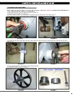
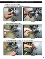
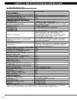
9.13 loWER CoNTRol BoARD REPlACEMENT
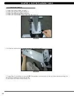
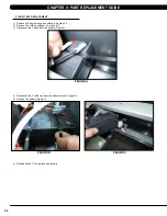
1) Remove the front shrouds as outlined in Section 9.8.
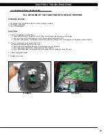
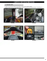
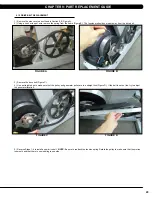
2) Disconnect the 5 wire connections to the lower board (Figure A).
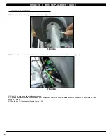
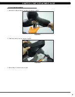
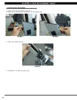
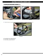
3) Remove the 2 screws holding the lower board to the frame (Figure B), and remove the lower board.
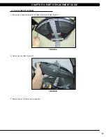
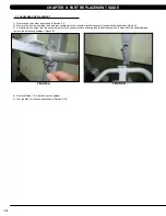
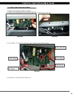
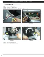
4) Reverse Steps 1-3 to install a new lower board. Figure C shows the connections at the board.
5) Test the bike for function as outlined in Section 9.20.
fIgURE A
fIgURE B
fIgURE C
3 Pin Connector from
the Generator
2 Pin Connector
from the Resistor
8 Pin Connector
from the Console
6 Pin Connector from
the DC power source
2 Pin Connector
from the Battery
CHAPTER 9: PART REPlACEMENT gUIDE
Содержание U5x-05
Страница 1: ...U 5 x 0 5 B I K E S E R V I C E M A N U A l...
Страница 4: ...1 1 1 Serial Number Location Chapter 1 Serial Number Location fRAME Serial number location...
Страница 17: ...14 8 1 Electrical Diagrams Chapter 8 Troubleshooting...
Страница 18: ...15 Chapter 8 Troubleshooting 8 1 electrical diagramS CONTINUED...
Страница 19: ...16 8 1 Electrical Diagrams CONTINUED Chapter 8 Troubleshooting MCB POWER Wire Digital Communication Wire...
Страница 20: ...17 Chapter 8 Troubleshooting 8 1 Electrical Diagrams CONTINUED pulse sensor wire rIGHT pulse sensor wire lEFT...
Страница 21: ...18 8 1 Electrical Diagrams CONTINUED Chapter 8 Troubleshooting PULSE extended WIRE...
Страница 63: ...60 final assembly 10 2 assembly instructions continued Chapter 10 bike specifications and assembly guide...
Страница 72: ...69 NOTES...


