MSC-XDM1000S Product Manual
1.2.1 Installing Video I/O Boards
Once the I/O boards have been identified as either Input or Output modules, refer to the following installation
instructions.
Installation Instructions
1. Input and Output modules should be installed in sequential board slots beginning from the first slot
which will be labeled
INPUTS 1-8
or
OUTPUTS 1-8
respectively. Identify the board slots where the
boards will be installed and remove cover plates (if any), by removing the 4 mounting screws.
2. If the router is not currently mounted in a rack, installation may be easier with the router placed face
down on a table on something soft (to protect the front panel). If the router is already mounted,
installation can still be performed, but the I/O boards will need to be inserted horizontally, which makes
finding the card connector by feel slightly more difficult.
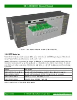
3. Ensuring the correct type of board is being used for a slot (Input or Output), position the board
connector first (opposite side of the BNC connectors) and board main component side towards the top of
the router, as depicted in Figure 5. Insert the card until it makes contact with the main crosspoint board
backplane. The card may need to be tilted up or down until it mates correctly with the main board
connector. It is important not to apply too much pressure when inserting the card, or damage may result
if the connector is not mating correctly. The board metal mounting plate should be flush against the
back of the router.
4. Once the I/O board is properly connected and the mounting plate is flush against the back of the router,
install the 4 mounting screws to hold it in place.
5. Repeat steps 3 and 4 for the remaining I/O boards.
Page 9 of 64
© 2013-2018 Matrix Switch Corporation
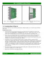
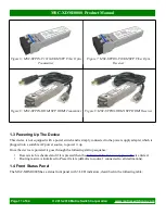
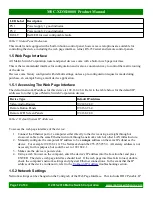
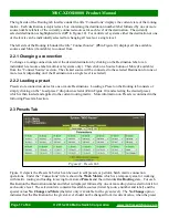
Figure 4: MSC-CARDTX-SFP8 SDI SFP Output
Module
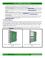
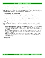
Figure 3: MSC-CARDTX-BNC8 SDI BNC Output
Module


