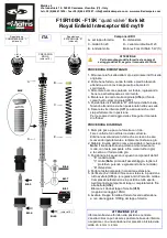
ASSEMBLY INSTRUCTIONS
1
-
Remove the front forks from the bike and remove
the original internal fork kit.
2
-
Thoroughly clean sleeve, fork tube and bottom avoiding
all damages to oil seals and guide bushings
3
-
Re
-
assemble bushings and oil seals on the sleeve
and add grease to all sliding parts.
4
-
Keep the original Top
-
Out
-
Spring
(ref.6)
and the
original bottom End
-
Stroke (hydro
-
stop)
(ref.7)
.
5
-
Position the fork kit “D” inside the fork tube.
Make sure it is firmly on its bottom base.
6
-
Tighten the lower screw
(ref.1)
and make sure the
fork kit lines up perfectly inside the fork tube.
Note:
for the tightening torques, follow the service
manual.
AIR BLEEDING INSTRUCTIONS
1
-
Slowly pour oil into the fork so that it flows inside the
cartridge.
Slide the rod up and down several times to bleed any
air bubbles out of the cartridge.
2
-
Adjust the oil level according to the setup card.
Note:
the oil level must be measured without spring
and the rod pushed completely down.
3
-
Position the fork kit parts as following:
-
“E” spring washer
-
“C” spring (
Note:
before assembly, remove the
protective, cleaning and degreasing well the spring)
-
“B” spring spacer
4
-
Take the pumping rod to the maximum extention.
5
-
(ref.3)
Check that the locking nut on the shaft is in the
all screwed position and make sure that the adjustments
of Compression / Rebound are in the full open position
and the spring preload aduste full unloading.
(ref.4)
Screw the cap to the damper rod completely
up the stop.
(ref.5)
Tighten the nut to the fork cap.
(Spanner 16 / Torque load 10 Nm)
6
-
Screw the fork cap onto the fork tube (make sure you
do not damage the O
-
ring placed on the fork cap).
FORK KIT PARTS
A
-
Fork cap unit
B
-
Spring spacer
C
-
Spring 36
-
320
D
-
Hydraulic cartridge
E
-
Spring washer Motorex Fork Oil SAE 5 W
COMPRESSION
ADJUSTMENT “C”
(tool 4)
REBOUND
ADJUSTMENT “R”
(tool 4)
ATTENTION
To remove the fork and tightening torques,
follow the service manual
ATTENTION (ref 2)
The stop spring is supplied at the center position.
The locking ring can be moved in the lower or upper seat
with a variation of the initial spring preload.
(decrease of
-
4 mm / increase of +4 mm)
C
A
E
D
B
Ref.2
Ref.3
Ref.5
Ref.4
ENG
Matris srl
Via Industriale 12
-
36043 Camisano Vicentino (VI)
-
Italy
tel +39 (0)444 411636
-
fax +39 (0)444 411887
-
-
www.matrisdampers.com
(tool 16)
Rif.1
Rif.7
Rif.6
SPRING
PRELOADING
ADJUSTER
(tool 19)
F15R100K
-
F15K
“quad valve”
fork kit
Royal Enfield Interceptor 650 my19


